
Fixture and method for opening oblique holes in steel pipes

A tooling fixture and steel pipe technology, applied in the direction of manufacturing tools, clamping, positioning devices, etc., can solve the problems of inconvenience, poor manual flame cutting and shape, unsightly appearance of steel pipe openings, etc., to achieve convenient use and improve hole making accuracy. And work efficiency, saving the effect of railing construction

Active Publication Date: 2015-08-12
MCC5 GROUP CORP SHANGHAI
View PDF10 Cites 0 Cited by
  • Summary
  • Abstract
  • Description
  • Claims
  • Application Information

AI Technical Summary

Problems solved by technology

The known steel pipe hole opening methods cannot process inclined holes, and the manual flame cutting is not good, and the steel pipe hole appearance is not beautiful, but in the actual railing processing, both situations need to be figure 1 Make oblique holes on the pole as shown, so that the small tube (knee pad) can pass through the oblique holes according to the requirements of the designer
[0003] Therefore, there are above-mentioned inconveniences and problems in the known steel pipe perforating method.

Method used


Image

  • Fixture and method for opening oblique holes in steel pipes
  • Fixture and method for opening oblique holes in steel pipes
  • Fixture and method for opening oblique holes in steel pipes

Examples


Embodiment 1

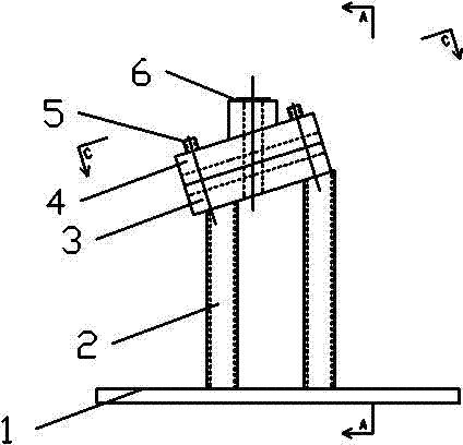
[0035] The tooling fixture for opening inclined holes in steel pipes of the present invention comprises a fixture base 1, two fixture pillars 2, a lower die 3, an upper die 4 and four fastening bolts 5, and is characterized in that:

[0036] The fixture base 1, a steel plate with a thickness of 40mm, is used as the platform plate of the fixture base;

[0037] The two clamp pillars 2 are 18mm channel steels with different lengths and spacing between them, which are respectively perpendicular to the clamp base 1, one end of which is welded and fixed to the clamp base 1, and the other end is arranged as an oblique top;

[0038] The lower mold 3 is a mold with a groove in the middle of the longitudinal direction and a through-hole for drilling in the middle of the groove, and its two ends are welded and fixed to the oblique top ends of the two fixture pillars 2 respectively;

[0039] Described patrix 4, a mold that is provided with groove in the middle of the longitudinal directio...


PUM


Abstract

The invention discloses a frock clamp for drilling a steel pipe inclined hole, which comprises a clamp base (1), two clamp columns (2), a lower die (3), an upper die (4) and four fastening bolts (5). The frock clamp is characterized in that: the clamp base (1) is a steel plate with a thickness of 30-50mm; the two clamp columns (2) have different lengths and a spacing therebetween, and are vertical to a 16 or 18mm groove steel of the base (1) respectively, and one ends of the two clamp columns are welded and fixed with the base (1) while the other ends of the two clamp columns are set into inclined top ends; a groove is arranged longitudinally in the middle of the lower die (3), a mould of a through hole is arranged at the middle part of the groove, and the two ends of the lower die are welded and fixed with the inclined top ends of the two clamp columns (2) respectively; a mould of the groove is arranged longitudinally in the middle of the upper die (4) matched with the lower die (3), and a drill head inlet hole (6) is arranged at the middle part of the upper die (4); and two of the four fastening bolts (5) are arranged at the two ends of the upper and lower dies respectively so as to connect and fix the upper and lower dies.

Description

technical field [0001] The invention relates to a method for drilling steel pipe holes, in particular to a fixture and method for drilling inclined holes in steel pipes. Background technique [0002] In the current processing of railing poles, because the stairs are inclined upward, the corresponding poles are vertical to the ground, and some are perpendicular to the handrails. Both of these situations require oblique holes to be made on the vertical poles, and radial drills or manual flame cutting are generally used for steel pipe holes, so that all straight holes perpendicular to the pipe wall are made. The known steel pipe hole opening methods cannot process inclined holes, and the manual flame cutting is not good, and the steel pipe hole appearance is not beautiful, but in the actual railing processing, both situations need to be figure 1 As shown, the vertical pole is made with oblique holes, so that the small tube (knee pad) can pass through the oblique holes accordin...

Claims


Application Information

Patent Timeline
Patent Type & Authority Patents(China)
IPC IPC(8): B23B47/28B23Q3/06
Inventor 汪鸿洋魏来刁腾达
Owner MCC5 GROUP CORP SHANGHAI
Learn More