
Capacitive voltage-division type self-calibration optical voltage transducer

A technology of capacitive voltage divider and optical voltage sensing, which is applied in the direction of measuring current/voltage, voltage/current isolation, instruments, etc., can solve the problems of measurement accuracy temperature drift, poor anti-interference ability, etc., and eliminate the hidden danger of ferromagnetic resonance , The insulation structure is simple, and the effect of solving the poor temperature stability of the measurement accuracy

Inactive Publication Date: 2012-05-09
HARBIN INST OF TECH
View PDF4 Cites 28 Cited by
  • Summary
  • Abstract
  • Description
  • Claims
  • Application Information

AI Technical Summary

Problems solved by technology

[0005] The present invention aims to solve the problem of temperature drift of measurement accuracy and poor anti-interference ability in existing capacitive voltage-dividing optical voltage transformers, and proposes a capacitive voltage-dividing type self-calibrating optical voltage transformer Transformer

Method used


Image

  • Capacitive voltage-division type self-calibration optical voltage transducer
  • Capacitive voltage-division type self-calibration optical voltage transducer
  • Capacitive voltage-division type self-calibration optical voltage transducer

Examples


specific Embodiment approach 1

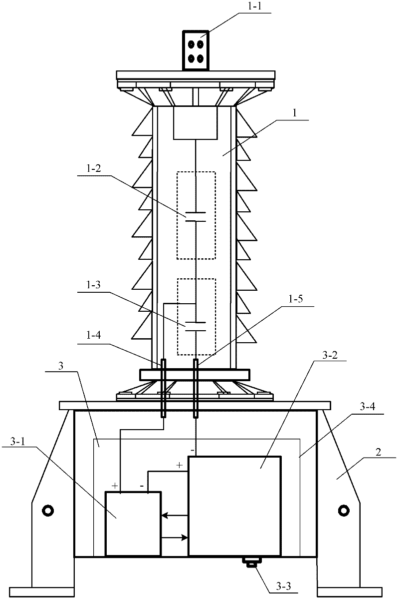
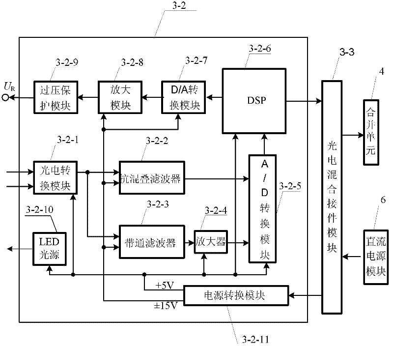
[0019] Specific implementation mode 1. Combination figure 1 and figure 2 Describe this embodiment, a capacitive voltage divider type self-calibration optical voltage transformer, it includes capacitive voltage divider 1, base 2 and optical voltage sensor 3, capacitive voltage divider 1 includes high-voltage capacitor 1-2, low-voltage capacitor 1- 3. The signal output terminal 1-4 and the ground terminal 1-5, the optical voltage sensor 3 includes an optical voltage sensing unit 3-1, the lower end of the high-voltage capacitor 1-2 is connected in series with the upper end of the low-voltage capacitor 1-3, and the capacitance is divided into One end of the signal output terminal 1-4 of the transformer 1 is connected with the positive pole of the optical voltage sensing unit 3-1, the other end of the signal output terminal 1-4 is connected with the upper end of the low-voltage capacitor 1-3, and the low-voltage capacitor 1- The lower end of 3 is connected with one end of the gro...

specific Embodiment approach 2

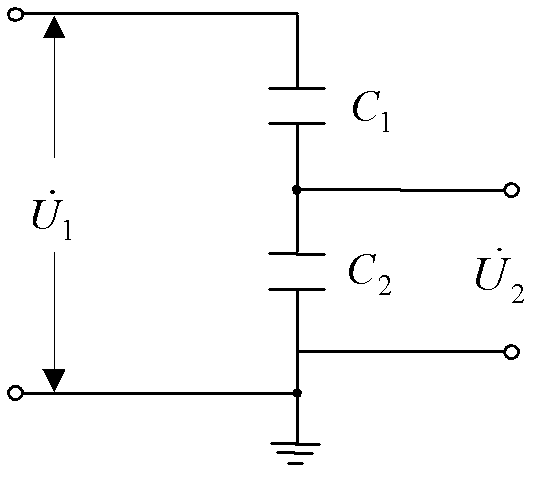
[0040] Specific implementation mode two, combining image 3 Describe this embodiment. The difference between this embodiment and the first embodiment is that the capacitive voltage divider 1 is composed of 2N identical capacitor elements, where N is a positive integer, and a capacitor elements are formed in series in a stacked series manner. The high-voltage capacitor 1-2 and b capacitor elements are stacked and connected in parallel to form a low-voltage capacitor 1-3, wherein a and b are both positive integers, and a+b=2N.

[0041] In this embodiment, the equivalent principle diagram of the capacitor voltage divider is shown as image 3 As shown, the capacitance of the high voltage capacitor 1-2 is C 1 , the capacitance of the low-voltage capacitor 1-3 is C 2 , the voltage division ratio of the capacitor voltage divider 1 is:

[0042] In this embodiment, the capacitive voltage divider 1 adopts a special symmetrical packaging structure of the upper and lower coupling cap...

specific Embodiment approach 3

[0043] Embodiment 3. The difference between this embodiment and Embodiment 1 is that the optical voltage sensor 3 further includes a shielding cover 3-4, and the shielding cover 3-4 covers the optical voltage sensing unit 3-1 and the signal processing unit. 3-2 outside.

[0044] In this embodiment, the shielding cover 3-4 can realize the shielding of external electromagnetic interference, and improve the anti-interference ability of the capacitive voltage dividing type self-calibrating optical voltage transformer of the present invention.


PUM


Abstract

The invention discloses a capacitive voltage-division type self-calibration optical voltage transducer, which is used for solving the problem that the existing capacitive voltage-division type optical voltage transducer generates measurement accuracy temperature drift under the influence of temperature and is poor in interference rejection. The capacitive voltage-division type self-calibration optical voltage transducer comprises a capacitive voltage divider, a base and an optical voltage sensor, the capacitive voltage divider comprises a high-voltage capacitor, a low-voltage capacitor, a signal output terminal and a grounding terminal; the optical voltage sensor comprises an optical voltage sensing unit, and further comprises a signal processing unit; and the signal processing unit comprises a photoelectric conversion module, an anti-aliasing filter, a band-pass filter, an amplifier, an A / D (analogue / digital) conversion module, a DSP (Digital Signal Processor),a D / A conversion module, an amplifying module, an overvoltage protection module, an LED (Light-Emitting Diode) light source, a power conversion module, a combining unit and a direct current power module, and further comprises a photoelectric hybrid connector module. The capacitive voltage-division type self-calibration optical voltage transducer is used for voltage measurement in an electric power system.

Description

technical field [0001] The invention relates to a capacitive voltage dividing type self-calibrating optical voltage transformer. Background technique [0002] Voltage transformer is an important equipment for voltage measurement in power system, and its measurement accuracy and operation reliability are closely related to the safe, reliable and economical operation of the power system. Based on Pockels electro-optic effect, optical voltage transformer is the most ideal electronic voltage transformer and the main direction of electronic voltage transformer. [0003] According to different sensing structures, optical voltage transformers can be divided into full-voltage optical voltage transformers, laminated dielectric voltage divider optical voltage transformers, capacitive voltage divider optical voltage transformers, and distributed optical voltage transformers. The most practical prospect is the capacitive voltage divider type optical voltage transformer. The capacitive...

Claims


Application Information

Patent Timeline
IPC IPC(8): G01R15/18G01R19/00
Inventor 郭志忠张国庆于文斌路忠峰申岩王贵忠李深旺
Owner HARBIN INST OF TECH
Learn More