Liquefied natural gas (LNG) low-temperature liquefied primary refrigerating four-stream spiral twined pipe type heat exchange equipment

A spiral-wound, tube-type heat exchange technology, which is applied in the field of LNG low-temperature liquefaction first-stage refrigeration four-stream spiral-wound tube-type heat exchange equipment, can solve problems such as pipeline leakage, large volume, and poor self-shrinking ability

Inactive Publication Date: 2014-04-16
张周卫
View PDF9 Cites 0 Cited by
  • Summary
  • Abstract
  • Description
  • Claims
  • Application Information

AI Technical Summary

Problems solved by technology

At present, most mixed-refrigerant natural gas liquefaction systems adopt an integral heat exchange method, which connects the three-stage refrigeration process as a whole. The height of the heat exchanger can reach 60-80 meters, and the heat exchange efficiency has been significantly improved. The technological process is too complicated, and the volume of the heat exchange equipment is too large, which brings serious inconvenience to the processing and manufacturing, on-site installation and transportation, and once there are problems such as pipeline leakage, it is difficult to detect, and it is easy to cause the entire heat exchanger to be scrapped and the complete set of process equipment to stop production
In addition, because ordinary tube-and-tube heat exchangers adopt the tube-sheet connection parallel tube bundle method, the structure is simple, and the self-shrinking ability is poor. Generally, the heat exchange is performed by a single flow, the heat exchange efficiency is low, the volume is large, and the temperature difference is small. Cool and liquefy natural gas in one process

Method used


Image

  • Liquefied natural gas (LNG) low-temperature liquefied primary refrigerating four-stream spiral twined pipe type heat exchange equipment

Examples


Embodiment Construction

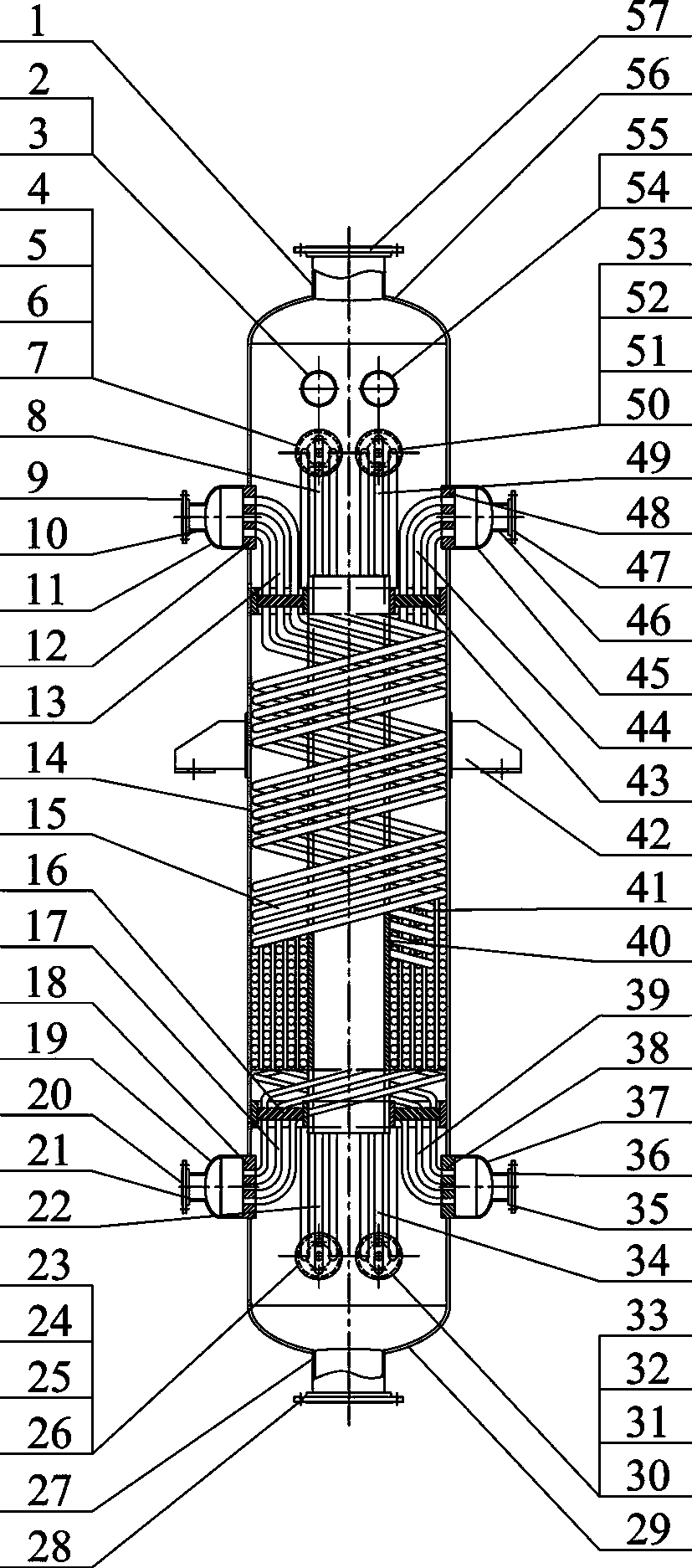
[0015] 36°C, 0.9MPa C4H separated from the mid-stage condensation of the mixed refrigerant compressor 10 — Different C 4 h 10 The mixed refrigerant enters the tube box 25 and is distributed in the tube box 25 at C 4 h 10 — Different C 4 h 10 C 3 h 8 、C 4 h 10 — Different C 4 h 10 , The -63°C, 0.3MPa N that enters the shell from the connecting pipe 1 2 —CH 4 —C 2 h 4 The mixed gas is supercooled, the temperature drops to -53°C, the pressure drops to 0.6MPa, and then flows to the pipe box 6, and the throttle valve installed between the connecting pipe 5 and the connecting pipe 2 is throttled into a supercooled liquid. After throttling, the pressure down to 0.3MPa, the temperature becomes -52.85°C, and then enters the cylinder 14 through the connecting pipe 2, and the throttled C 3 h 8 , N entering the shell from the connecting pipe 1 2 —CH 4 —C 2 h 4 The mixed gas is mixed, and after mixing, it flows downward to cool the natural gas tube bundle 39, N 2 —CH ...


PUM


Abstract

The invention belongs to the technical field of liquefied natural gas (LNG) low-temperature liquefaction, and relates to LNG primary low-temperature refrigerating equipment and a mixed refrigerant refrigerating technology. Natural gas at the temperature of 36 DEG C and under the pressure of 6.1MPa is cooled so as to enter a secondary pre-cooling stage at the temperature of 53 DEG C below zero in a four-stream spiral twined pipe type heat exchanger by using a refrigerant of C3H8 and C4H10-iso-C4H10 and an N2-CH4-C2H4 mixed gas under the pressure of 0.3MPa and at the temperature of 63 DEG C below zero at an LNG secondary outlet; and the C3H8 and the C4H10-iso-C4H10 are sub-cooled by using the twined pipe type heat exchanger, throttled to a shell pass and mixed with the N2-CH4-C2H4 to pre-cool a natural gas pipe bundle, an N2-CH4-C2H4 pipe bundle, a sub-cooling C3H8 pipe bundle and a C4H10-iso-C4H10 pipe bundle, so that the aims of primary natural gas pre-cooling, N2-CH4-C2H4 mixed gas pre-cooling and sub-cooling before the C3H8 and the C4H10-iso-C4H10 are throttled are fulfilled. The equipment has a compact structure and high heat exchange efficiency, can be applied in the field of phase change low-temperature heat exchange of gas zones at the temperature of between 36 DEG C and 53 DEG C below zero, solves the technical problem of primary refrigeration of LNG, and improves the low-temperature heat exchange efficiency of an LNG system.

Description

technical field [0001] The invention belongs to the technical field of low-temperature liquefaction of natural gas, and relates to LNG primary low-temperature refrigeration equipment and mixed refrigerant refrigeration technology. 3 h 8 、C 4 h 10 — Different C 4 h 10 Refrigerant and LNG secondary outlet 0.3MPa, N at -63°C 2 —CH 4 —C 2 h 4 The mixed gas cools the 36°C, 6.1MPa natural gas to -53°C in the four-stream spiral wound tube heat exchanger to enter the secondary pre-cooling section; the wound tube heat exchanger is used to supercool C 3 h 8 、C 4 h 10 — Different C 4 h 10 , then throttling to the shell side and N 2 —CH 4 —C 2 h 4 Pre-cooled natural gas tube bundle after mixing, N 2 —CH 4 —C 2 h 4 Tube bundle, supercooled C 3 h 8 Bundle and C 4 h 10 — Different C 4 h 10 Tube bundle, to achieve first-level natural gas precooling, mixed gas N 2 —CH 4 —C 2 h 4 pre-cooling and C 3 h 8 、C 4 h 10 — Different C 4 h 10 The purpose of subcoo...

Claims


Application Information

Patent Timeline
Patent Type & Authority Patents(China)
IPC IPC(8): F25J5/00
Inventor 张周卫汪雅红张小卫庞凤皎李振国鲁小军李瑞明万续
Owner 张周卫
Why Eureka
Try Eureka