Permanent-magnet surface-mounted motor rotor with fixed plates

A technology of motor rotor and stator, applied in the direction of magnetic circuit rotating parts, magnetic circuit shape/style/structure, etc., can solve the problems of high rotor temperature, permanent magnet, large loss of fixed plate, low motor efficiency, etc., and achieve reduction Small rotor heats up, improves motor efficiency, and reduces loss

Inactive Publication Date: 2012-05-16
HANGZHOU ZHONGSHANG ENERGY TECH
View PDF7 Cites 7 Cited by
  • Summary
  • Abstract
  • Description
  • Claims
  • Application Information

AI Technical Summary

Problems solved by technology

However, the fixing method of this permanent magnet has always been a difficult problem for the surface-mounted permanent magnet rotor. Especially when the motor speed is high, the permanent magnet and the fixed piece will generate large losses, and due to the use of a metal protective sleeve, there will be Eddy current loss, the temperature of the rotor is higher, and the efficiency of the motor is lower

Method used


Image

  • Permanent-magnet surface-mounted motor rotor with fixed plates
  • Permanent-magnet surface-mounted motor rotor with fixed plates
  • Permanent-magnet surface-mounted motor rotor with fixed plates

Examples


Embodiment 1

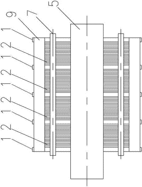
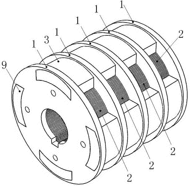
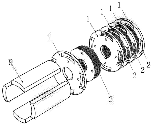
[0021] Embodiment 1: The permanent magnet surface-mounted motor rotor of this example has a fixed piece, such as figure 1 , figure 2 , image 3 , there are some fixed plates 1, and the fixed plates are made of iron. An iron core sheet 2 is arranged between two adjacent fixed sheets, and the iron core sheet is made of silicon steel laminations with a certain thickness. Such as Figure 4 , The middle part of the fixed piece has a fixed piece axis hole 3. Such as Figure 5 , the middle part of the iron core sheet has an iron core sheet shaft hole 4 that is consistent with the shape of the shaft hole of the fixed sheet, and a shaft body 5 is connected in the shaft hole to fix all the fixed sheets and the iron core sheets together. The fixed sheet shaft hole, the iron core sheet shaft Fastening holes 6 are evenly distributed on the fixed piece and the iron core piece around the hole, and a fixed rod 7 is connected in the fastening hole. The diameter of the fixed piece is larg...

Embodiment 2

[0023] Embodiment 2: The permanent magnet surface-mounted motor rotor of this example has a fixed piece, such as Figure 6 , Figure 7 , there are some fixed plates 1, and the fixed plates are made of iron. An iron core sheet 2 is arranged between two adjacent fixed sheets, and the iron core sheet is made of silicon steel laminations with a certain thickness. Such as Figure 4 , The middle part of the fixed piece has a fixed piece axis hole 3. Such as Figure 5 , the middle part of the iron core sheet has an iron core sheet shaft hole 4 that is consistent with the shape of the shaft hole of the fixed sheet, and a shaft body 5 is connected in the shaft hole to fix all the fixed sheets and the iron core sheets together. The fixed sheet shaft hole, the iron core sheet shaft Fastening holes 6 are also evenly distributed on the fixed piece and the iron core sheet on the periphery of the hole, and a fixed rod 7 is pierced in the fastening hole. The diameter of the fixed piece is...


PUM


Abstract

The invention relates to the field of motor design and manufacture, in particular to a permanent-magnet surface-mounted motor rotor with fixed plates. The motor rotor mainly aims to solve the technical problems that when the motor in prior art has relatively high rotational speed, both the permanent magnets and the fixed plates have comparatively large loss, and the use of the metal protective sleeve causes eddy current loss, relatively high temperature of the rotor and relatively low efficiency of the motor, and the like. The motor rotor of the invention comprises a plurality of fixed plates, wherein iron core plates are arranged between the adjacent two fixed plates; fixed plate shaft holes are positioned in the middle of the fixed plates respectively; iron core plate shaft holes consistent to the fixed plate shaft holes in form are arranged in the middle of the iron core plates respectively; shaft bodies are positioned in the shaft holes so as to fix all fixed plates and the iron core plates together; fastening holes are further distributed on the fixed plates and the iron core plates uniformly at peripheries of the fixed plate shaft holes and the iron core shaft holes; fixed rods are positioned in the fastening holes; more than two grooves or holes are distributed at the outer edges of the fixed plates uniformly; and the permanent magnets are positioned in the grooves or the holes of the fixed plates.

Description

technical field [0001] The invention relates to the field of motor design and manufacture, in particular to a permanent magnet surface-mounted motor rotor with a fixed piece. Background technique [0002] Permanent magnet motors have the advantages of high efficiency and high power density, and have recently received more and more attention. Among them, the surface-mounted permanent magnet rotor has become the most widely used rotor structure in permanent magnet motors because of its simple structure and convenient manufacture. A Chinese patent discloses an improved permanent magnet motor rotor (authorized announcement number: CN202004552U), which includes a rotor core, a tile-type permanent magnet, a built-in permanent magnet, and a rotating shaft, and a "V"-shaped groove is opened in the rotor core , the tile-type permanent magnet is pasted on the surface of the rotor core, and the built-in permanent magnet is inserted in the "V" groove in the rotor core; the polarity of ...

Claims


Application Information

Patent Timeline
Patent Type & Authority Applications(China)
IPC IPC(8): H02K1/28
Inventor 王灿飞沈建新金孟加
Owner HANGZHOU ZHONGSHANG ENERGY TECH
Why Eureka
Try Eureka