Engine exhaust energy recovery device, ship provided therewith, and power generation plant provided with said engine exhaust energy recovery device

A technology for recycling devices and engines, which can be used in exhaust devices, mechanical equipment, engine components, etc., and can solve problems such as inability to improve thermal efficiency.

Inactive Publication Date: 2012-05-23
MITSUBISHI HEAVY IND LTD +1
View PDF8 Cites 19 Cited by
  • Summary
  • Abstract
  • Description
  • Claims
  • Application Information

AI Technical Summary

Problems solved by technology

On the other hand, in an engine, there is a restriction that the scavenging pressure cannot be made higher than the allowable pressure in order to operate the engine safely.
Therefore, there is a problem that thermal efficiency cannot be improved even if high-pressure scavenging air is supplied to the engine.

Method used


Image

  • Engine exhaust energy recovery device, ship provided therewith, and power generation plant provided with said engine exhaust energy recovery device
  • Engine exhaust energy recovery device, ship provided therewith, and power generation plant provided with said engine exhaust energy recovery device
  • Engine exhaust energy recovery device, ship provided therewith, and power generation plant provided with said engine exhaust energy recovery device

Examples


no. 1 approach

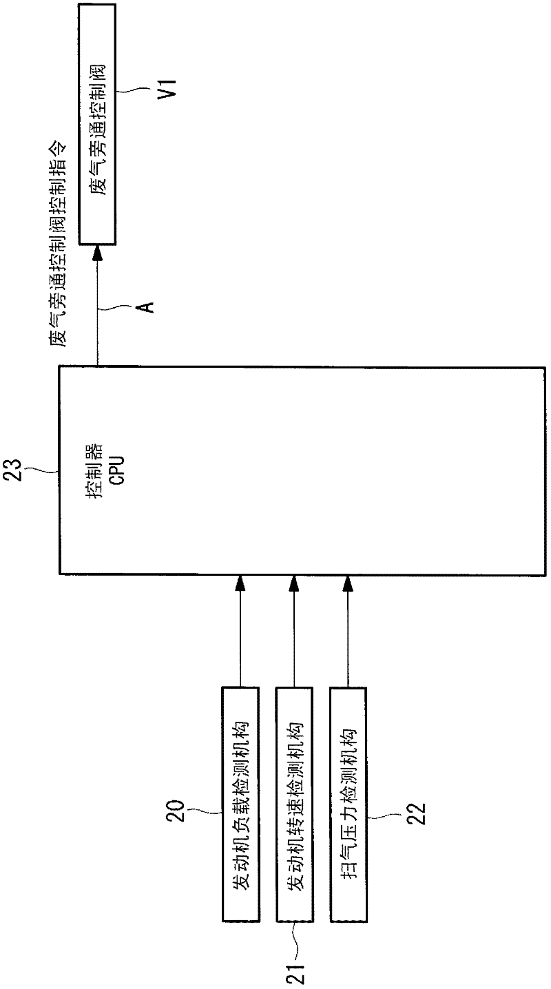
[0096] refer to image 3 and Figure 4 A first embodiment of the control method of the present invention for controlling the fuel consumption rate to a predetermined value or less will be described. image 3 is a control configuration diagram related to this embodiment, Figure 4 It is a control flowchart related to this embodiment.

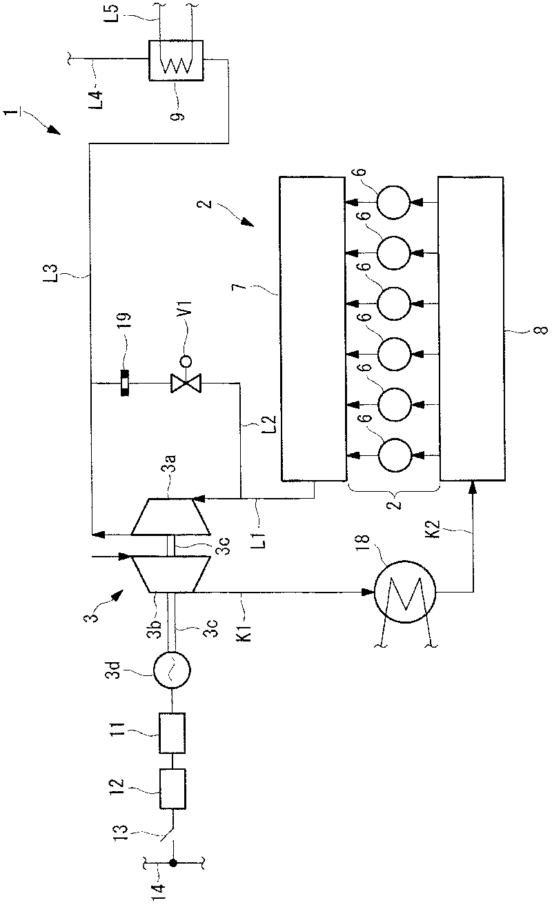
[0097] exist image 3 , the engine main body 4 detected by the engine load detection mechanism 20 (refer to figure 1 ), the engine main body 4 rotational speed signal detected by the engine rotational speed detection mechanism 21, and the scavenging pressure signal detected by the scavenging pressure detection mechanism 22 are input to the controller (control device) 23. Based on the input signals, the controller 23 outputs a wastegate control valve control command signal A to the wastegate control valve V1.

[0098] Such as Figure 4 As shown, in step S1 , the signals of the engine load L, the engine speed Ne, and the scavenging pressure P...

no. 2 approach

[0113] Next, refer to Figure 5 and Figure 6 A second embodiment of the control method of the present invention for controlling the fuel consumption rate to a predetermined value or less will be described. In the first and second embodiments, the cylinder internal pressure is not measured, but the control is performed based on the scavenging pressure detected by the scavenging pressure detection means. On the other hand, in Embodiments 3 and 4 described later, it is the case where the control is performed to measure the pressure in the cylinder.

[0114] Figure 5 is a control configuration diagram related to this embodiment, Figure 6 It is a control flowchart related to this embodiment.

[0115] exist Figure 5 In the reference numerals, the same reference numerals are assigned to the same configuration, flow of exhaust gas, flow of air, and control method as those of the first embodiment. The control method differs from the first embodiment in that a wastegate valve ...

no. 3 approach

[0136] Next, refer to Figure 7 , Figure 8A and Figure 8B A third embodiment of the control method of the present invention for controlling the fuel consumption rate to a predetermined value or less will be described. Figure 7 is a control configuration diagram related to this embodiment, Figure 8A and Figure 8B It is a control flowchart related to this embodiment.

[0137] exist Figure 7 , Figure 8A and Figure 8B In the reference numerals, the same reference numerals are attached to the same structures as those of the second embodiment, the flow of exhaust gas, the flow of air, and the control method. The control method differs from the second embodiment in that the cylinder internal pressure signal detected by the cylinder internal pressure detection mechanism 27 is input to the controller 28 .

[0138] exist Figure 8A and Figure 8BIn step S21 of the shown flowchart, in addition to inputting the wastegate control valve opening degree signal B detected by ...


PUM


Abstract

Provided is an engine exhaust energy recovery device wherein it is possible to reduce the fuel consumption rate of an engine to a predetermined level or lower in relation to the various engine loads and the number of revolutions of the engine, and to effectively use the exhaust gas which is emitted from the engine. The engine exhaust energy recovery device is provided with: a hybrid supercharger (3) which has a turbine section (3a) to which the exhaust gas emitted from an engine (2) is supplied, a compressor section (3b) which compresses and transfers a scavenging pressure to the engine (2), and a power generator/electric motor section (3d) which generates power when the turbine (3a) is driven; a bypass path (L2) which bypasses the exhaust gas that is supplied to the hybrid supercharger (3); and a control device which has a database for calculating the scavenging pressure, in which the fuel consumption rate of the engine (2) is at a predetermined level or lower, on the basis of the detection values obtained from the detection means including an engine load detection means, an engine revolution number detection means, and a scavenging pressure detection means. The control device controls an exhaust gas bypass control valve (V1) in order to control the scavenging pressure of the engine (2).

Description

technical field [0001] The present invention relates to an engine exhaust energy recovery device for recovering exhaust energy of exhaust gas discharged from an engine as power, a ship provided with the engine exhaust energy recovery device, and a power generation facility provided with the ship. Background technique [0002] A supercharger and a power turbine are known as exhaust energy recovery devices that recover exhaust energy contained in exhaust gas discharged from an engine as power (for example, Patent Document 1). [0003] prior art literature [0004] patent documents [0005] Patent Document 1: Japanese Patent Application Laid-Open No. 63-186916 [0006] However, the invention described in Patent Document 1 supplies exhaust gas used for driving the power turbine to the exhaust turbine of the supercharger when the output of the power turbine is reduced during high-load operation of the engine. Therefore, the driving force and the rotational speed of the exhaust...

Claims


Application Information

Patent Timeline
Patent Type & Authority Applications(China)
IPC IPC(8): F02B37/18F01N5/02F02B37/10F02D13/02F02D23/00F02D23/02F02D41/04F02D45/00
CPCF02D41/0007F02B39/10F02D29/02F02D2250/34F02D2041/001F02D2200/024F01N5/04F02B37/18F02D35/023Y02T10/144F01N5/02Y02T10/16Y02T10/12F02B37/10F02D13/02
Inventor 村田聪樋口纯
Owner MITSUBISHI HEAVY IND LTD
Why Eureka
Try Eureka