Image capture device and image capture method

A camera device and image technology, applied in projection devices, printing devices, measuring devices, etc., can solve problems such as the decrease in shooting sensitivity, and achieve the effects of suppressing computing costs, simple camera structure, and reducing computing costs

Active Publication Date: 2012-05-23
PANASONIC CORP
View PDF9 Cites 17 Cited by
  • Summary
  • Abstract
  • Description
  • Claims
  • Application Information

AI Technical Summary

Problems solved by technology

In other words, the shooting sensitivity of the camera is greatly reduced
[0017] 3. Need to calculate the cost

Method used


Image

  • Image capture device and image capture method
  • Image capture device and image capture method
  • Image capture device and image capture method

Examples


Embodiment approach 1

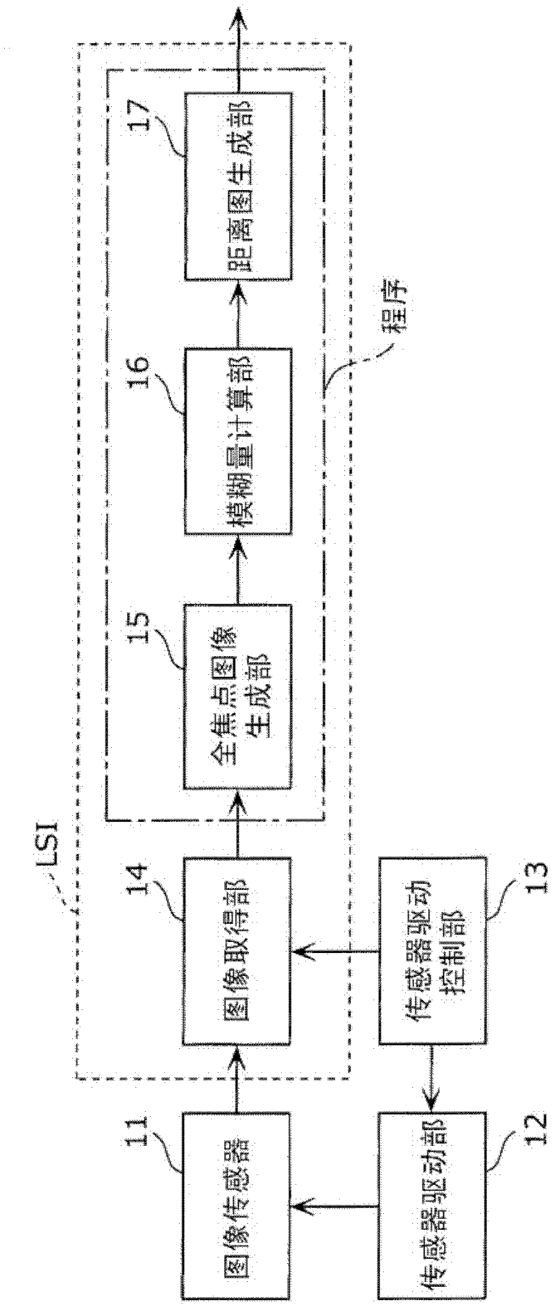
[0046] figure 1 A block diagram showing the imaging device according to Embodiment 1 of the present invention.

[0047] exist figure 1 Among them, the imaging device includes an image sensor 11 , a sensor drive unit 12 , a sensor drive control unit 13 , an image acquisition unit 14 , an all-focus image generation unit 15 , a blur amount calculation unit 16 , and a distance map generation unit 17 . In the configuration of the imaging device, the constituent units that can be mounted on a single-chip integrated circuit are indicated by dotted lines. However, since the image acquisition unit 14 is a memory, it may be a separate body from the above-mentioned integrated circuit. In addition, among the configurations of the imaging device, constituent units that can be realized by a program are surrounded by dashed-dotted lines.

[0048] The image sensor 11 is CMOS, CCD, etc., converts the light received by the imaging surface into an electric signal for each pixel, and outputs ...


PUM


Abstract

Disclosed is an image capture device that generates a distance map to a photographic subject from a photographic image, with high precision. Three images are photographed with a sensor drive unit (12) and a sensor drive controller unit (13), which move an image sensor (11) in the optical axis direction: photographic images (A, C) that are respectively focused on the near-end side and the far-end side of the photographic subject, and an image (B) that is photographed while sweeping the image sensor from the near-end side to the far-end side. An omnifocal image (D) is generated by an omnifocal image generator unit (15) from the sweep image (B); a blur quantity in each component region of the image (A) and the image (B) is computed by a blur quantity computation unit (16), carrying out a deconvolution process with an image of a region corresponding to the omnifocal image (D); and the distance from the device to the photographic subject in each image region, i.e., a distance map, is generated by a distance map generator unit (17) from the blur quantity of the regions corresponding to the near-end image (A) and the far-end image (C) and optical coefficients of the image capture device, including the focal length of the lens.

Description

technical field [0001] The present invention relates to an imaging device or an imaging method for measuring the distance between a subject and the imaging device from a captured image. Background technique [0002] As a conventional method of measuring the distance between a subject and an imaging device from a captured image, there is generally known a DFD (Depth From Defocus: Defocus Distance Measurement) method of estimating a distance using the blur of an observed image (e.g. , refer to Non-Patent Document 1). In the DFD method proposed in Non-Patent Document 1 (hereinafter referred to as "Pentland method"), focusing on the edge of the image, the amount of blur is estimated from one or two observation images containing blur, and the amount of blur is estimated from the amount of blur. The distance to the subject. However, in this method, the edge information of the image of the subject is required in advance, and blur caused by the lens occurs in the observation image...

Claims


Application Information

Patent Timeline
Patent Type & Authority Applications(China)
IPC IPC(8): G01C3/06G02B7/28G03B13/36H04N5/232
CPCG01C3/32G02B7/365G03B3/10H04N5/23212G03B13/36G06T7/0069H04N5/2226G06T7/571H04N23/959
Inventor 田川润一杉谷芳明河村岳木村雅之
Owner PANASONIC CORP
Why Eureka
Try Eureka