Polymer actuator and valve using the same

An actuator and polymer technology, applied in the field of polymer actuators, can solve problems such as complex internal structure, deterioration of efficiency, wear of sealing parts and sliding parts, and achieve high sealing performance, ensure sealing performance, and prevent sliding

Inactive Publication Date: 2015-08-05
KITZ CORP
View PDF8 Cites 0 Cited by
  • Summary
  • Abstract
  • Description
  • Claims
  • Application Information

AI Technical Summary

Problems solved by technology

[0009] However, in the shaft seal device using the sealing member, when the closed area and the non-sealed area are switched, the contact and sliding of the operating mechanism are accompanied, so the sealing member and the sliding part are prone to wear and tear, and it is difficult to ensure sufficient sealing performance.
Therefore, this shaft sealing device is not suitable for the opening and closing of the flow path and flow control
[0010] In addition, the valve of Patent Document 1 requires the pressure resistance of the EPAM and a strong sealing force because the entire EPAM bears the fluid pressure when the fluid is closed.
In addition, other sealing mechanisms are required in the main body, or valve seats need to be provided, and the internal structure becomes complicated.
In addition, since the electrode is arranged on the entire surface of the polymer film application area of ​​this valve, when the polymer film is used as a movable part such as a valve body or an actuator of the valve body, the deformation of the applied energy The quantity decreases and the efficiency deteriorates
In this way, the valve is used for a valve with a smaller diameter, which is not practical in the case of controlling the flow of a large flow

Method used


Image

  • Polymer actuator and valve using the same
  • Polymer actuator and valve using the same
  • Polymer actuator and valve using the same

Examples


Embodiment 1

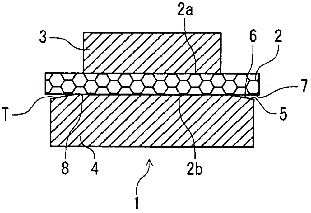
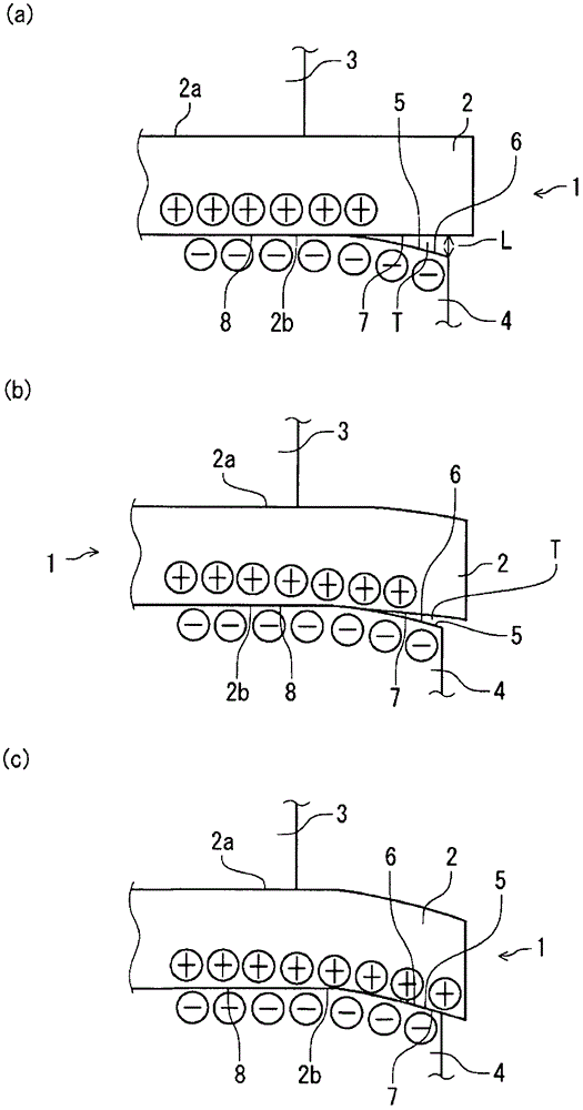
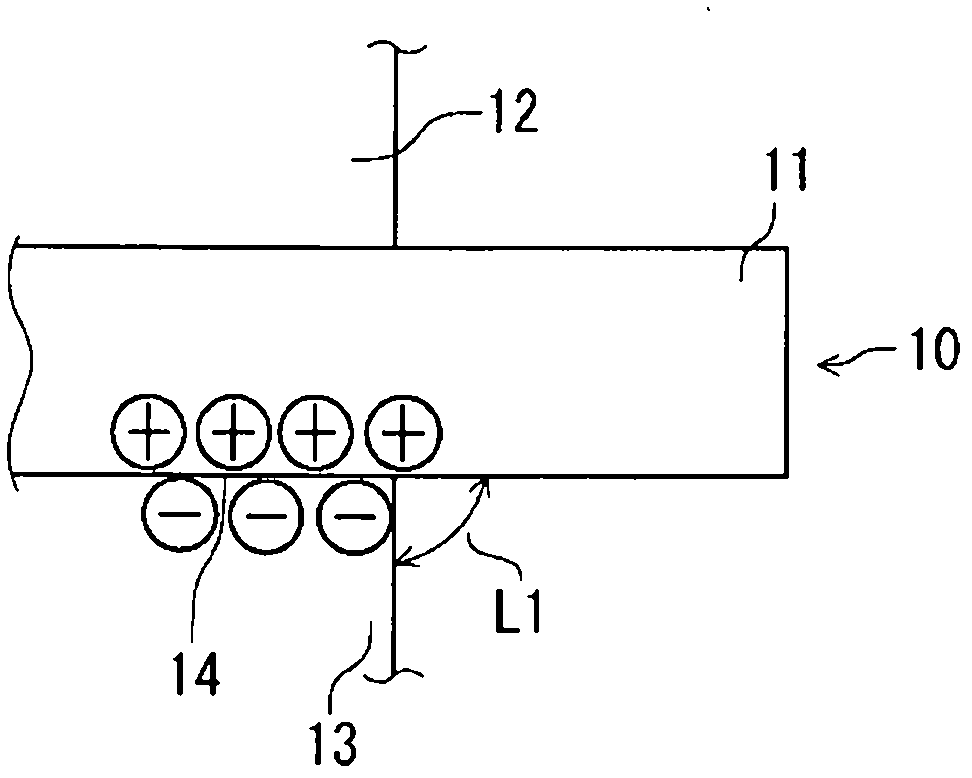
[0206] Will figure 1 The shown actuator body 1 with the fixed electrode 4 with the arcuate surface 6 is formed as Figure 16 The actuator body 1 was used as a test product A, and the displacement of the driving body 2 was measured by the above-mentioned displacement measuring device 100 . On the other hand, as a comparison of the actuator main body 1, the image 3 The illustrated actuator part 10 is formed as Figure 17 The dimensions shown were used as a comparative product a, and the displacement amount of the driving body portion 11 was measured in the same manner. Figure 16 The driver 2 in Test Sample A is composed of ester-based polyurethane to which 0.5 wt % of tetrabutylammonium chloride is added, and is formed to have a diameter of 20 mm and a thickness of 0.1 mm. On the other hand, an inclined surface 6 is formed on the negative side fixed electrode 4 , and the entire positive side fixed electrode 3 is fastened to the driver 2 .

[0207] The state of voltage appl...

Embodiment 2

[0210] will be Figure 7 The shown actuator body 40 with flexible electrodes 41, 42 formed on the driving body 2 with the arcuate surface 6 is formed as Figure 20 , and use it as test item B. The driver 2 in the test sample B is composed of ester-based polyurethane to which 0.5 wt % of tetrabutylammonium chloride is added, and is formed to have a diameter of 20 mm and a thickness of 0.1 mm. On the driver 2, a gold thin film was formed on the negative side with a diameter of 16 mm or less by sputtering, and a gold thin film was formed on the entire surface of the positive side by sputtering. On the other hand, the above-mentioned arcuate surface 6 is formed as an inclined surface on the negative side fixed electrode 4 , and the entire positive side fixed electrode 3 is fastened to the driver 2 .

[0211] Figure 21 In, means relative to image 3 The actuator part of is used as the comparison product b of the actuator part 16 formed with the flexible electrode parts 14 and ...

Embodiment 3

[0220] Next, put Figure 7 The actuator body 40 is formed as Figure 28 The size of the test product E is used as the test product E, and the applied voltage is stepped up by 0.1kV each time, so that the deformed part of the driving body 2 is bent and displaced until it meets the arc surface 6 of the fixed electrode 4 After the contact, the applied voltage was lowered stepwise by 0.1 kV each time. The change in the voltage at this time and the change in the displacement of the driving body are represented by Figure 29 middle.

[0221] according to Figure 29 As a result of the measurement, even at the same applied voltage, the amount of displacement may be different when the applied voltage is raised and lowered, and the locus of the change in the amount of displacement is different when the voltage rises and falls. That is, when the applied voltage was raised to 0.7kV, the displacement increased, but when the applied voltage was lowered to 0.7kV, the shape did not return...


PUM


Abstract

The object is to provide a polymer actuator capable of securing high sealability in spite of a simple interior structure, controlling opening and closing of the fluid passage or flow rate while increasing the amount of displacement at a small amount of applied voltage, and controlling the flow rate from small flow rate to large flow rate through variation in the applied voltage, thereby enhancing response performance and to provide a valve using the polymer actuator. The polymer actuator includes a power driver 2 deformed upon receiving external electro stimuli and fixed electrodes 3 and 4 disposed on upper and lower surface sides of the power driver 2 in an opposite manner for applying positive and negative external electro stimuli to the power driver 2 in a planar fashion, wherein at least one of the fixed electrodes 3 and 4 extends to a side, on which the power driver is bent and deformed, and has an abutment surface 5 displaced by means of the Coulomb force when the power driver 2 has been deformed, thereby enabling the abutment surface to come into contact with the power driver and, at the time of application of no external electro stimuli, the abutment surface 5 of one of the fixed electrodes forms a spaced-apart region T between itself and the power driver 2.

Description

technical field [0001] The present invention relates to a polymer actuator using a polymer material and a valve suitable for opening and closing a flow path and controlling the flow rate using the polymer actuator. Background technique [0002] Conventionally, for example, when the fluid is always sealed as the control of the flow path in the container, a shaft sealing device using a sealing member such as an O-ring is generally used. Since the first purpose of this shaft sealing device is to improve the sealing function by the sealing member, generally the sealing member and the fluid sealing area are determined at predetermined positions. Therefore, assuming that the closed area is switched to the non-enclosed area through the shaft sealing device, and the opening and closing of the flow path and the flow control are to be performed, it is necessary to set threaded inlets at the sealing parts, housings and other assembly parts of the closed area. To other action agencies ...

Claims


Application Information

Patent Timeline
Patent Type & Authority Patents(China)
IPC IPC(8): H02N2/00F16K31/02
CPCH01L41/094F16K31/02H01L41/193F16K31/406F16K31/404H10N30/2042H10N30/2047H10N30/857
Inventor 山崎知哉
Owner KITZ CORP
Why Eureka
Try Eureka