Manufacturing method for chip-resistant plate of lower tube seat

A manufacturing method and a technology for a lower tube seat, which are applied in the field of the manufacture of chip anti-chip plates for the lower tube seat, can solve the problems of difficult discharge of the anti-chip plate galvanic corrosion products, low working efficiency, large electrode loss, etc., so as to solve the problem of large local electrode loss and improve The effect of reducing work efficiency and processing area

Inactive Publication Date: 2012-05-30
CNNC JIANZHONG NUCLEAR FUEL
View PDF3 Cites 4 Cited by
  • Summary
  • Abstract
  • Description
  • Claims
  • Application Information

AI Technical Summary

Problems solved by technology

[0004] The invention solves the technical problems that the electric corrosion products of the existing anti-chip boards are difficult to be discharged in time, and the frequent secondary discharge causes large local loss of electrodes and low working efficiency.

Method used


Image

  • Manufacturing method for chip-resistant plate of lower tube seat
  • Manufacturing method for chip-resistant plate of lower tube seat
  • Manufacturing method for chip-resistant plate of lower tube seat

Examples


Embodiment 1

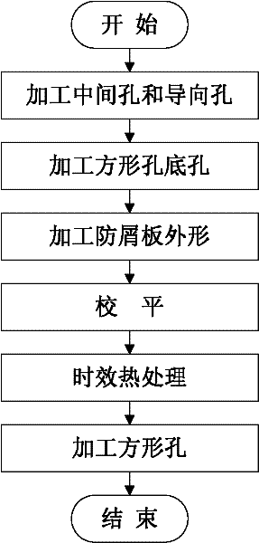
[0040] like figure 1 As shown, the method for manufacturing the chip-proof plate of the lower pipe seat of the present embodiment includes the following steps:

[0041] Step 1. Process the middle hole 1 and the guide hole 2;

[0042] Step 2. Process the bottom hole of the square hole;

[0043] Step 3. Process the shape of the anti-chip board;

[0044] Step 4. Leveling;

[0045] Step 5. Aging treatment;

[0046] Step 6. Process the square hole.

Embodiment 2

[0048] The method for manufacturing the chip-proof plate of the lower pipe seat in this embodiment includes the following steps:

[0049] Step 1. Machining middle hole 1 and guide hole 2:

[0050] Step 1.1. Pre-processing the middle hole 1 and the guide hole 2:

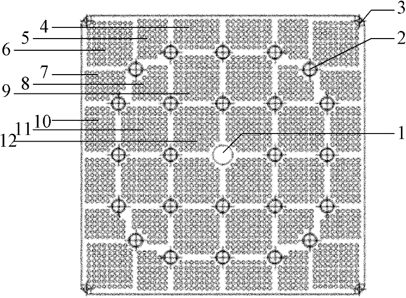
[0051] Step 1.1.1 Use a drill bit with a diameter of 8 mm to drill the middle hole 1 at the center of the chip guard, wherein the preferred thickness of the chip guard is 3 mm;

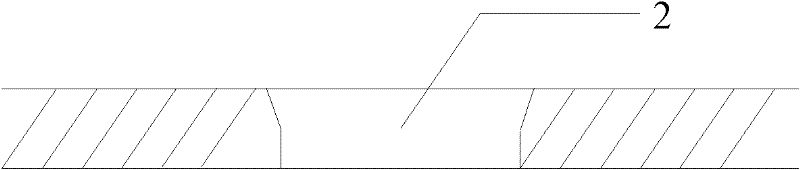
[0052] Step 1.1.2. If figure 2 As shown, take the center of the middle hole 1 as the coordinate origin and the unit distance is 1mm in the coordinate system, respectively (0, ± a), (0, ± b), (± a, 0), (± b, 0) , (±a, ±a), (±b, ±b), (±b, ±a), (±c, ±c) a total of 24 coordinates are circle points, use a drill with a diameter of 8mm to drill the pilot hole 2 ; Wherein, 35≤a≤40, 72≤b≤78, 60≤c≤65. For example: a=37.72, b=75.44, c=62.87; or a=35, b=72, c=60; or a=40, b=78, c=65.

[0053] Step 1.2. Finishing middle hole 1 and pilot hole 2:

[...

Embodiment 3

[0067] The difference between this embodiment and embodiment 2 is:

[0068] The EDM machine described in step 6 adopts combined electrodes, and the combined electrodes include that the number and positions of the electrodes correspond to the number and positions of the bottom holes of the square holes of the anti-chip plate. When drilling square holes, all the bottom holes of square holes can form square holes at one time under the action of combined electrodes, thus avoiding the process of replacing electrodes and processing one by one, and the time for manufacturing a chip-proof board is reduced from 30 hours to 8 hours, which is great Improved work efficiency.


PUM

PropertyMeasurementUnit
diameteraaaaaaaaaa

Abstract

The invention belongs to the technical field of chip-resistant plates, and particularly relates to a manufacturing method for a chip-resistant plate of a lower tube seat. The technical scheme of the invention comprises the following steps of: processing a middle hole and a guide hole; processing a bottom square hole; processing the appearance of the chip-resistant plate; leveling; performing ageing treatment; and processing a square hole. Due to the adoption of the manufacturing method, the technical problems of high local electrode loss and low working efficiency caused by frequent secondary discharge since an electrical erosion product is difficult to discharge in time in the conventional chip-resistant plate are solved. According to the invention, the processing area of an electric spark machine tool is reduced by 80 percent, the electrical erosion product is discharged in time, and high local electrode loss caused by frequent secondary discharge is avoided; and moreover, the square hole is processed by adopting a combined electrode, so that replacement of an electrode is avoided, maintenance is facilitated, and working efficiency is greatly increased.

Description

technical field [0001] The invention belongs to the technical field of anti-chip boards, and in particular relates to a method for manufacturing an anti-chip board for a lower pipe seat. Background technique [0002] The anti-chip plate of the lower tube seat is mainly used to prevent foreign matter in the circuit from entering the fuel assembly and causing damage to the fuel rods, and has the function of distributing the flow. [0003] The anti-chip board generally consists of a middle hole in the center, several guide holes scattered on the anti-chip board, and thousands of square holes. The square hole in the existing anti-chip board adopts a one-time forming process, that is, the square hole is directly drilled to the required size. This method of manufacturing the anti-chip board makes it difficult to discharge the electrical corrosion products in time, and then causes frequent secondary discharges to cause large local loss of electrodes. Problem; In addition, the manu...

Claims


Application Information

Patent Timeline
Patent Type & Authority Applications(China)
IPC IPC(8): B23P15/00
Inventor 任宇宏张世平李曦刘嘉郭翔
Owner CNNC JIANZHONG NUCLEAR FUEL
Why Eureka
Try Eureka