Method for manufacturing alignment film for liquid crystal, method for manufacturing liquid crystal element, apparatus for manufacturing alignment film for liquid crystal, liquid crystal element

A manufacturing method and a technology of an alignment film, applied in nonlinear optics, instruments, optics, etc., can solve problems such as high material costs, high processing costs, and complex manufacturing processes, and achieve high anchoring strength, excellent controllability, and long-term stability sex high effect

Active Publication Date: 2016-06-22
STANLEY ELECTRIC CO LTD
View PDF7 Cites 0 Cited by
  • Summary
  • Abstract
  • Description
  • Claims
  • Application Information

AI Technical Summary

Problems solved by technology

However, when using the technology disclosed in Patent Document 1, although the expected pretilt angle of 0° to 90° can be obtained, the manufacturing process is complicated compared with the use of anisotropic dry etching, so the processing cost is high, and because more different materials (particles, resins, etc.), so the cost of materials is high, and there is still room for improvement in these aspects

Method used


Image

  • Method for manufacturing alignment film for liquid crystal, method for manufacturing liquid crystal element, apparatus for manufacturing alignment film for liquid crystal, liquid crystal element
  • Method for manufacturing alignment film for liquid crystal, method for manufacturing liquid crystal element, apparatus for manufacturing alignment film for liquid crystal, liquid crystal element
  • Method for manufacturing alignment film for liquid crystal, method for manufacturing liquid crystal element, apparatus for manufacturing alignment film for liquid crystal, liquid crystal element

Examples


no. 1 Embodiment approach

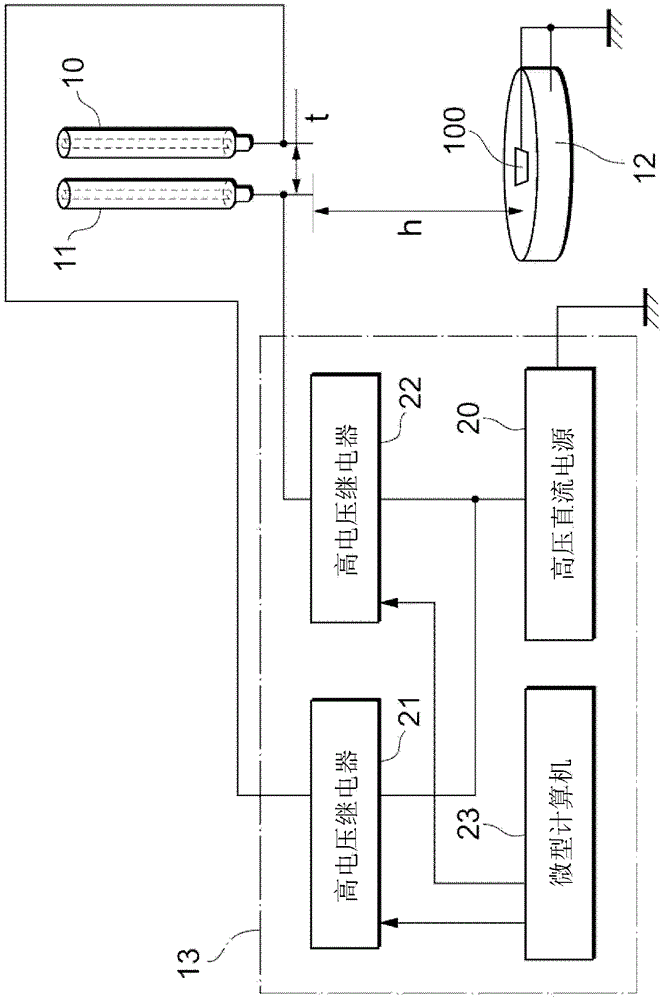
[0044] figure 1 It is a schematic diagram showing the structure of the manufacturing apparatus of the alignment film of 1st Embodiment. figure 1 The manufacturing apparatus of the alignment film shown has two spraying devices 10, 11, a substrate holder (substrate holder) (substrate fixing unit) 12, and a voltage applying device 13, and the two spraying devices 10, 11 have a cylindrical shape, etc. A syringe (barrel) for holding a material liquid of an alignment film (hereinafter referred to as "alignment film liquid") inside and a hollow microneedle provided at one end of these syringes, the substrate holder ( The substrate fixing unit) 12 is used to hold the substrate 100 , which is the object for forming an alignment film by these spraying devices 10 , 11 , and the voltage applying device 13 is used to apply voltage to each spraying device 10 , 11 . As shown in the figure, the injection device 10 and the injection device 11 are arranged adjacent to each other. The voltage ...

Embodiment 1

[0065] A pair of glass substrates (thickness of ITO: 1500 angstroms, glass plate thickness: 0.7 mm, glass material: non-alkali glass) on which transparent electrodes such as ITO were formed were prepared. These substrates were cleaned, and ITO was patterned using a normal photolithography process. Here, wet etching (ferric chloride) was used as the ITO etching method.

[0066] Next, on the glass substrate on which the ITO was patterned, the alignment film liquid (orientation material) was sprayed by the electrospray deposition method. A mixed solution of a horizontal alignment material (manufactured by PI-A Nissan Chemical Industry Co., Ltd.: 4 wt %) and a solvent (methylene chloride) is filled in the syringe of one of the jetting devices 10, and a vertical alignment material is filled in the syringe of the other jetting device 11. A mixed solution of a material (Nissan Chemical Industry Co., Ltd. SE-1211: 4 wt %) and a solvent (DCM) was simultaneously sprayed from each of th...

Embodiment 2

[0072] As Example 2, a method of temporally and alternately dispersing different materials was studied. The same steps as in Example 1 were used except for the formation step of the alignment film. In the syringe of one of the injection devices 10, fill the mixed solution of the horizontal alignment material (PI-A identical to the above-mentioned embodiment 1: 4wt%) and the solvent (methylene chloride and γ-butyrolactone), and in another injection device Fill the syringe of 11 with a mixed solution of vertical alignment material (SE-1211 the same as the above-mentioned Example 1: 4wt%) and solvent (dichloromethane and γ-butyrolactone), and the spraying devices 10 and 11 time-divisionally Each mixed solution was dispersed. Specifically, the microcomputer 23 selectively controls the high voltage relays 21 and 22 to be on at a predetermined time ratio, and the high voltage DC power supply 20 applies voltage to the needles of the injection devices 10 and 11 . Each cycle (spreadi...


PUM

PropertyMeasurementUnit
particle diameteraaaaaaaaaa

Abstract

The present invention relates to a method for producing an alignment film for liquid crystals, a method for producing a liquid crystal element, an apparatus for producing an alignment film for liquid crystals, and a liquid crystal element. An object of the present invention is to provide a new technology capable of setting the pretilt angle of liquid crystal molecules within a wide range. The present invention relates to a method for manufacturing an alignment film for liquid crystals. The method is used to manufacture an alignment film for liquid crystals on a substrate. Release the first material liquid in a state where a potential difference is relatively provided, so that the first material liquid forms a mist and spreads on the substrate; (b) a second step of relatively providing a potential between the second material liquid and the above-mentioned substrate In the poor state, the second material liquid is released, so that the second material liquid forms a mist and spreads on the substrate; and (c) a third step, solidifies the first material liquid and the second material liquid spread on the substrate.

Description

technical field [0001] The invention relates to a technology for controlling the orientation of liquid crystal molecules in a liquid crystal element. Background technique [0002] The orientation control technology is one of the elemental technologies in the manufacture of liquid crystal elements. Conventionally, as a technique for realizing a relatively high pretilt angle, for example, the technique disclosed in JP-A-6-95115 (Patent Document 1) is known. However, when using the technology disclosed in Patent Document 1, although the expected pretilt angle of 0° to 90° can be obtained, the manufacturing process is complicated compared with the use of anisotropic dry etching, so the processing cost is high, and because more There are many kinds of materials (particles, resins, etc.), so the cost of materials is high, and there is still room for improvement in these aspects. In addition, the alignment film for the liquid crystal element is a molecularly designed material, so...

Claims


Application Information

Patent Timeline
Patent Type & Authority Patents(China)
IPC IPC(8): G02F1/1337G02F1/1333
Inventor 都甲康夫工藤幸宽高桥泰树
Owner STANLEY ELECTRIC CO LTD
Why Eureka
Try Eureka