Supercharge Your Innovation With Domain-Expert AI Agents!

Offset feed type radar antenna

A radar antenna and feed-type technology, applied in the field of bias-feed radar antenna, can solve the problems of complex process and production process of parabolic antenna, and achieve the effect of omitting complex manufacturing process, avoiding influence and simple structure

Active Publication Date: 2012-05-30
KUANG CHI INST OF ADVANCED TECH +1
View PDF3 Cites 4 Cited by
  • Summary
  • Abstract
  • Description
  • Claims
  • Application Information

AI Technical Summary

Problems solved by technology

[0006] The purpose of the present invention is to overcome the problem of complex production process of manufacturing parabolic antenna in the prior art, and provide a kind of offset radar antenna, which proposes a radar antenna with a simple structure and a flat reflector. The antenna has the advantage that the parabolic antenna can receive or transmit electromagnetic waves in a directional manner, and at the same time avoids the complicated process of producing the parabolic antenna

Method used


Image

  • Offset feed type radar antenna
  • Offset feed type radar antenna
  • Offset feed type radar antenna

Examples


Embodiment Construction

[0035] The present invention will be described in further detail below in conjunction with the embodiments and the accompanying drawings, but the embodiments of the present invention are not limited thereto.

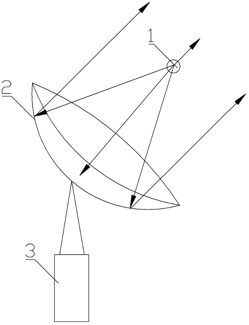
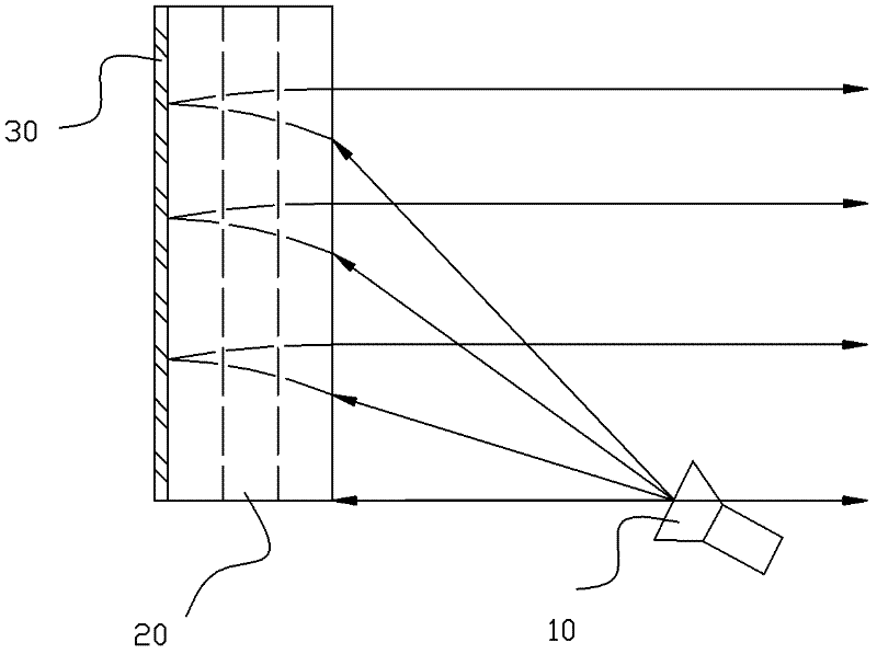
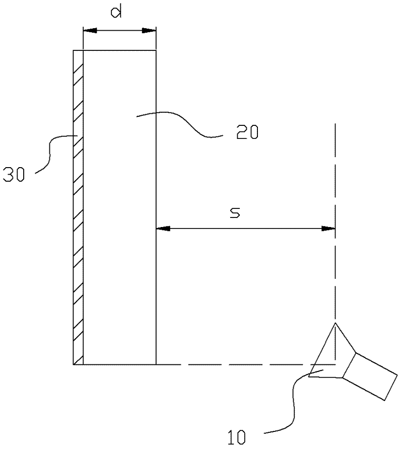
[0036] figure 2 with image 3 It is a structural schematic diagram of the bias-fed radar antenna of the present invention, and the antenna includes a feed source 10, a metamaterial panel 20, and a reflector 30, and the feed source 10 and the emitter panel 30 are respectively located on both sides of the metamaterial panel 20, reflecting The plate 30 is closely connected with the metamaterial panel 20 , and the orthographic projection of the point where the feed source 10 is located on the metamaterial panel 20 is the midpoint of the bottom edge of the metamaterial panel 20 .

[0037] Usually, the electromagnetic wave radiated from the feed source 10 is a spherical electromagnetic wave, but the far-field direction performance of the spherical electromagnetic wave is not...


PUM


Abstract

The invention relates to an offset feed type radar antenna, which comprises a feed source, a metamaterial panel and a reflective plate, wherein the feed source is positioned on the other side of the metamaterial panel and in the non-facing region of the metamaterial panel, the metamaterial panel comprises a plurality of core layers with the same refractive index distribution, and each core layer comprises a plurality of metamaterial units each having a unit basic material and an artificial microstructure. The offset feed type radar antenna greatly enhances antenna far-field power by changing the refractive index distribution in the metamaterial panel, so as to further improve an antenna transmission distance, and increases the front-to-rear ratio of the antenna to make the antenna more directional; furthermore, the invention uses the offset feed type radar antenna to prevent the feed source blocking the radiation of electromagnetic waves and the radiated electromagnetic waves affecting the feed source.

Description

technical field [0001] The invention relates to the field of radar antennas, in particular to a bias-feed radar antenna using metamaterials. Background technique [0002] The radar antenna converts the spherical wave radiated by the feed source into a plane wave through the reflector, so as to realize directional reception or emission of electromagnetic waves. The reflector currently used is in the shape of a parabola, and the feed source is located near the focus of the reflector. [0003] The working principle of the radar antenna is similar to that of an optical mirror. The existing radar parabolic antenna is as figure 1 As shown, it includes a collapsible source 1, a parabolic reflector 2 and a bracket 3. A feed 1 for transmitting or receiving electromagnetic waves is placed at the focus of the parabolic reflector 2. Using the focusing characteristics of the parabolic reflector 2, the The spherical wave is reflected by the parabolic reflector 2 and converted into a plan...

Claims


Application Information

Patent Timeline
Patent Type & Authority Applications(China)
IPC IPC(8): H01Q15/00H01Q15/23H01Q19/06H01Q19/10
Inventor 刘若鹏季春霖岳玉涛洪运南
Owner KUANG CHI INST OF ADVANCED TECH
Features
  • R&D
  • Intellectual Property
  • Life Sciences
  • Materials
  • Tech Scout
  • Unparalleled Data Quality
  • Higher Quality Content
  • 60% Fewer Hallucinations
Learn More