Combined structure for magnetic steel and magnetic loop of motor

A technology of combined structure and magnetic circuit, applied in the direction of magnetic circuit shape/style/structure, magnetic circuit rotating parts, etc., can solve the problems of low pass rate, improper control of curing temperature, invisible cracks in magnetic steel, etc.

Inactive Publication Date: 2012-05-30
环宇平
View PDF0 Cites 1 Cited by
  • Summary
  • Abstract
  • Description
  • Claims
  • Application Information

AI Technical Summary

Problems solved by technology

The known defects of installation using this process method are: 1. The glue is not evenly applied, the surface of the magnetic steel is not cleaned thoroughly, the curing time is not enough, the curing temperature is improperly controlled, and the reliability is poor. The glue will be damaged due to high or low temperature. Failure, magnetic steel falls off, damages the motor, and causes serious consequences; the second method uses polymer one-time injection molding. The known defects of this method are: special injection molding machines and extremely complicated molding molds are used, and the investment cost of equipment and molds is extrem

Method used


Image

  • Combined structure for magnetic steel and magnetic loop of motor
  • Combined structure for magnetic steel and magnetic loop of motor
  • Combined structure for magnetic steel and magnetic loop of motor

Examples


specific Embodiment approach

[0012] Specific embodiments: the present invention will be further described below in conjunction with accompanying drawing

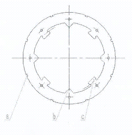
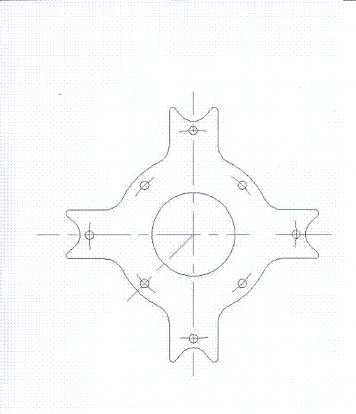
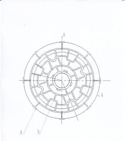
[0013] In the combined structure of a motor magnet and a magnetic circuit in the present invention figure 1 As shown, the dovetail groove set on the outer surface of the magnetic circuit ( figure 1 a) Each groove is used for one dovetail of the double dovetails on the fixed end plate to form a magnetic steel cavity with the same number of magnetic poles on the outer circular surface of the magnetic circuit for assembling the magnetic steel. V-shaped teeth set on the surface of the inner hole ( figure 1 b), for the rotor to bear radial force and positioning. In the middle of two adjacent V-shaped teeth, a rectangular boss ( figure 1 c), it can not only play a positioning role, but also bear part of the radial component force. figure 2 The supporting arm set on the outer diameter of the supporting iron core and the V-shaped groove at the end of the...


PUM

PropertyMeasurementUnit
Thicknessaaaaaaaaaa

Abstract

The invention relates to a combined structure for magnetic steel and magnetic loop of a motor, consisting of a magnetic loop, a support core, a fixed end plate and a rotating shaft, wherein a corresponding number of dovetail grooves are arranged according to the number of magnetic poles by the periphery of the magnetic circuit, V-shaped teeth bearing the radial torque are designed on the internal circular surface and supported on the external diameter of the core, a plurality of equal support arms are arranged, double dovetail locking pieces having the same number as that of the magnetic poles are arranged on the fixed end plate and on the external diameter of the plate. The method for processing the magnetic isolating piece into V shape by using the magnetic isolating material through a die can effectively overcome the drawbacks of the old-fashioned products during the production. The structure is simple and convenient to produce and process.

Description

technical field [0001] The invention relates to a rotor structure for a permanent magnet motor, in particular to a combined structure of a motor magnetic steel and a magnetic circuit. Background technique [0002] In the prior art, it is very common to use magnets as the magnetic poles of the rotor. There are generally two traditional methods for installing and fixing the magnets: one is the mounting method, which uses glue to attach the magnets to the rotor core. The known defects of installation using this process method are: 1. The glue is not evenly applied, the surface of the magnetic steel is not cleaned thoroughly, the curing time is not enough, the curing temperature is improperly controlled, and the reliability is poor. The glue will be damaged due to high or low temperature. Failure, magnetic steel falls off, damages the motor, and causes serious consequences; the second method uses polymer one-time injection molding. The known defects of this method are: special i...

Claims


Application Information

Patent Timeline
IPC IPC(8): H02K1/27H02K1/28
Inventor 环宇平
Owner 环宇平
Why Eureka
Try Eureka