Fume Extraction Hood

A hood and air exhaust technology, which is applied in the direction of oil fume removal, combustion product treatment, household heating, etc., can solve the problem of inability to discharge cooking oil fumes, and achieve the effect of small energy loss and weakened airflow effect

Inactive Publication Date: 2012-05-30
BERLING
View PDF13 Cites 23 Cited by
  • Summary
  • Abstract
  • Description
  • Claims
  • Application Information

AI Technical Summary

Problems solved by technology

In this way, the incoming air entering the kitchen space is directed into the suction outlet in a short-circuit operation, so that the incoming air cannot be used to effectively assist the extraction of cook

Method used


Image

  • Fume Extraction Hood
  • Fume Extraction Hood
  • Fume Extraction Hood

Examples


Embodiment Construction

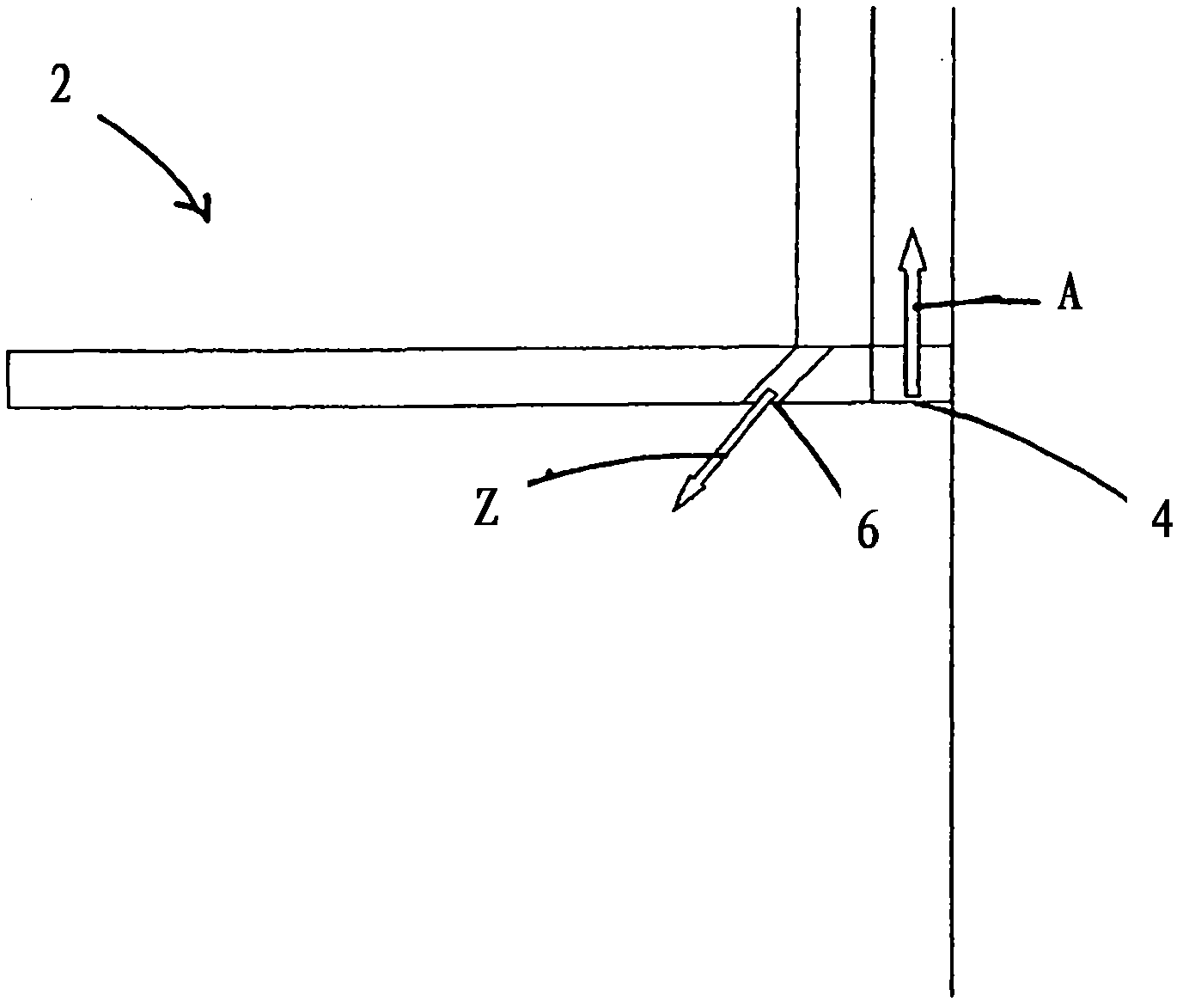
[0037] figure 1 The hood 2 fastened to the wall is shown in a schematic side view. The smoke extractor 2 has a suction outlet 4 and an air inlet 6 . The incoming air Z enters the galley space via the air inlet 6 , while the exhaust air A is sucked away from the galley space via the suction port 4 . In the schematic side view it can be seen that the inlet air Z and the outlet air A are oriented in opposite directions.

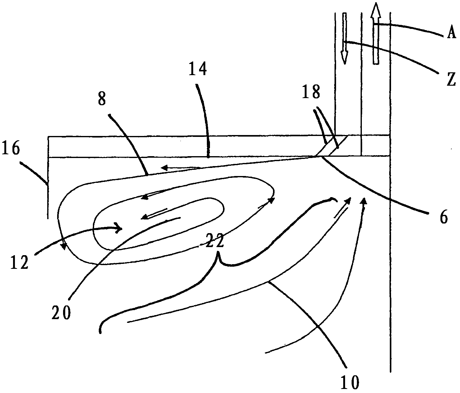
[0038] figure 2 The situation of the incoming air flow 8 and the outgoing air flow 10 is further shown in a schematic side view in FIG. from figure 2 It can be seen that the incoming air flow 8 exits the air inlet 6 and flows approximately in the direction of the outgoing air flow 10 . Starting from the air inlet, the incoming air flow 8 moves counter to the direction of flow of the outgoing air flow 10 and along the wall 14 present in the exemplary embodiment until the incoming air flow 8 reaches the region of the deflection surface 16 . Starting from t...


PUM


Abstract

The present invention relates to a fume extraction hood (2) having an exhaust opening (4) for leading away exhaust air (A) and an inlet opening (6) for feeding inlet air (Z), disposed adjacent to the exhaust opening (4). In order to achieve an inlet air guide, by means of which cooking vapors can be effectively captured and fed to the exhaust opening, the invention proposes that the inlet opening (6) is disposed and implemented so that the inlet air flow (8) flowing out of the inlet opening (6) in a direction oriented opposite to the flow direction of an exhaust gas flow (10) flowing into the exhaust opening (4), and the exhaust air flow (10) is deflected sideways via an extraction path (F).

Description

technical field [0001] The invention relates to a smoke extractor, which has a suction outlet for leading out exhaust air and an air inlet for introducing incoming air, the air inlet being arranged adjacent to the suction outlet. Background technique [0002] The hood has a high airflow delivery capacity in order to remove cooking fumes from the kitchen space as completely as possible. In conventional technology, in order to absorb all the cooking fumes, not only must the cooking fumes be sucked in, but many times the volume of air corresponding to said cooking fumes must also be expelled. [0003] In order to discharge unnecessarily much heated or cooled room air out of the building during operation of the smoke extractor and / or to prevent exhaust gases from combustion plants from being sucked into the interior of the building, it is known from the prior art: The appliance is provided with an air inlet through which outside air and / or ambient air is blown into the kitchen ...

Claims


Application Information

Patent Timeline
IPC IPC(8): F24C15/20
CPCF24C15/20F23J11/00F24F7/04F24F13/00
Inventor U·贝尔林
Owner BERLING
Why Eureka
Try Eureka