Charge pump feedback system with time sequence control function

A feedback system and timing control technology, applied in the direction of conversion equipment without intermediate conversion to AC, can solve problems such as carrier response malfunction, achieve the effect of easy circuit, solve interference problems, and simple structure

Active Publication Date: 2014-04-16
SHANGHAI HUAHONG GRACE SEMICON MFG CORP
View PDF2 Cites 0 Cited by
  • Summary
  • Abstract
  • Description
  • Claims
  • Application Information

AI Technical Summary

Problems solved by technology

Since the non-contact communication technology uses the carrier signal to carry the modulation signal for wireless transmission, if the turn-on and turn-off cycle of the charge pump 10 coincides with the cycle of the carrier signal, it may cause a malfunction of the carrier response

Method used


Image

  • Charge pump feedback system with time sequence control function
  • Charge pump feedback system with time sequence control function
  • Charge pump feedback system with time sequence control function

Examples


Embodiment Construction

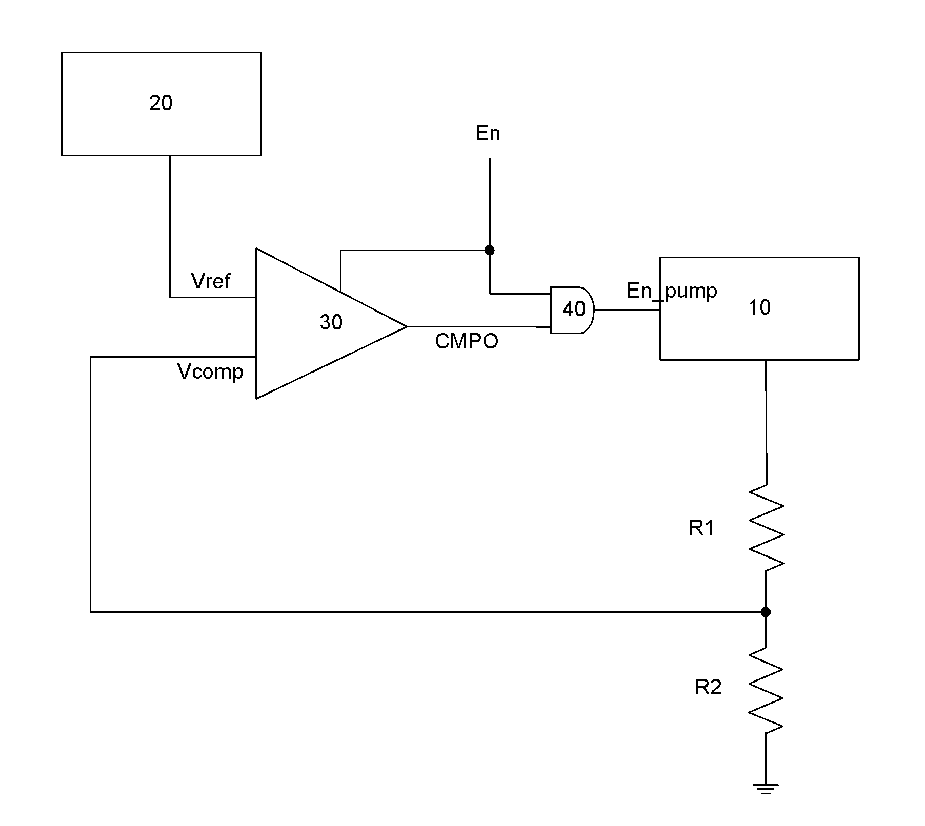
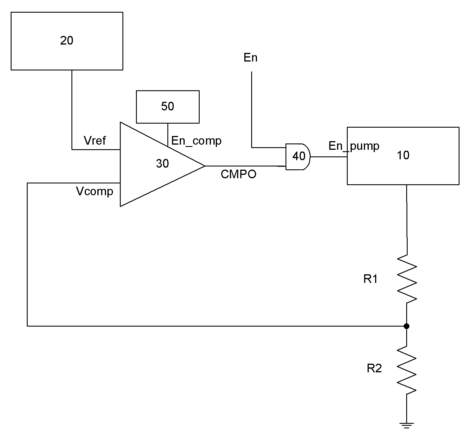
[0022] See image 3 , The charge pump feedback system with timing control of the present invention includes:

[0023] The charge pump 10, whose output voltage is grounded through a first resistor R1 and a second resistor R2 connected in series;

[0024] Band gap reference source 20, which outputs a reference voltage Vref;

[0025] In the comparator 30, the voltage output by the charge pump 10 is connected to one input terminal of the comparator 30 through the divided voltage Vcomp obtained by the first resistor R1 and the second resistor R2, and the reference voltage Vref is connected to the other input terminal of the comparator 30, When the comparator 30 is in the working state, when the divided voltage Vcomp is greater than or equal to the reference voltage Vref, the comparator 30 outputs the determination signal CMPO as logic 0, and when the divided voltage Vcomp is less than the reference voltage Vref, the comparator 30 outputs the determination signal CMPO as logic 1;

[0026] ...


PUM


Abstract

The invention discloses a charge pump feedback system. A time sequence control circuit is added on the basis of the traditional charge pump feedback system, and the time sequence control circuit outputs a control sequence to control starting of a comparator and a charge pump. Thus, real-time control is changed into time sequence control, and frequency control on power consumption fluctuation of the charge pump feedback system is realized. When the charge pump feedback system is applied to the non-contact communication field, the frequency of the control sequence is staggered from carrier frequency of non-contact communication. The charge pump feedback system with a time sequence control function disclosed by the invention has a simple structure, circuit and layout are easier to realize, and an interference problem of the charge pump feedback system when being applied to the non-contact field and other fields can be solved.

Description

Technical field [0001] The invention relates to a circuit of a charge pump feedback system. Background technique [0002] See figure 1 The existing charge pump feedback system includes a charge pump 10, a bandgap reference source 20, a comparator 30, an AND gate 40, a first resistor R1 and a second resistor R2. The specific structure is as follows: the enable signal En controls the opening or closing of the comparator 30. The enable signal En is also connected to an input terminal of the AND gate 40, and the AND gate 40 outputs a driving signal En_pump to control the opening or closing of the charge pump 10. The voltage output by the charge pump 10 is connected to an input terminal of the comparator 30 through the divided voltage Vcomp of the first resistor R1 and the second resistor R2. The reference voltage Vref output by the bandgap reference source 20 is connected to the other input terminal of the comparator 30. The decision signal CMPO output by the comparator 30 is conn...

Claims


Application Information

Patent Timeline
Patent Type & Authority Patents(China)
IPC IPC(8): H02M3/07
Inventor 朱瑶华王楠
Owner SHANGHAI HUAHONG GRACE SEMICON MFG CORP
Why Eureka
Try Eureka