Gas-liquid separator

A gas-liquid separator and separator technology, applied in separation methods, dispersed particle separation, chemical instruments and methods, etc., to achieve the effects of improved structure, improved processing capacity, and reliable operation

Inactive Publication Date: 2012-06-13
QINGDAO JINGRUN PETROCHEM DESIGN INST CO LTD
View PDF7 Cites 28 Cited by
  • Summary
  • Abstract
  • Description
  • Claims
  • Application Information

AI Technical Summary

Problems solved by technology

[0004]Shell Oil Company provides a gas-liquid separator in US7594942, which includes a vertically arranged shell with a gas-liquid mixture inlet, and a gas-liquid separation is arranged in the shell device, the gas-liquid separation device contains a gas-liquid inlet communicated with the housing inlet, an outlet for gas-liquid partial separation, a gas outlet for gas exiting the housing above the liquid and in the liquid and communicating with the outlet of the separation device, a A liquid storage chamber in the housing below the liquid and in the liquid that communicates with the outlet of the separation device, a liquid outlet with a liquid collection end in the liquid storage chamber of the housing, in the liquid storage chamber, the gas-liquid separation device has a vane inlet, A liquid collection tray is set between the gas-liquid separation device and the liquid storage chamber to form a collection area. In the collection area, the liquid impacts the tray from above the tray and flows from the collection area to the liquid storage chamber. The gas-liquid separator uses rotating blades to achieve primary separation , Use the foam breaking net to realize the second coalescence separation, and use the vortex tube to realize the third separation process, the separation effect is obvious, and the device structure is relatively complicated

Method used


Image

  • Gas-liquid separator
  • Gas-liquid separator
  • Gas-liquid separator

Examples


Embodiment approach 1

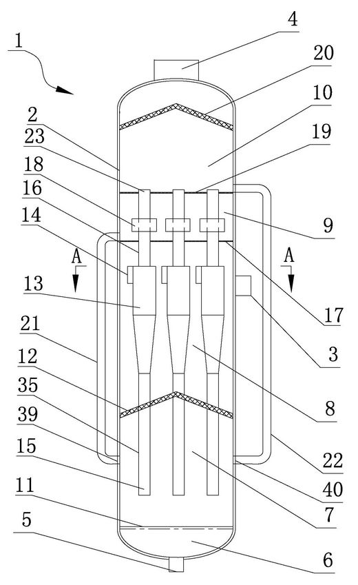
[0066] figure 1 It is a schematic diagram of the overall structure of the gas-liquid separator scheme 1 of the present invention, which adopts the gas-liquid separation process of the first-level cyclone separation, the second-level gas-lift pipe outlet ejection separation, and the third-level foam breaking net coalescence separation to realize the complete separation of gas and liquid;

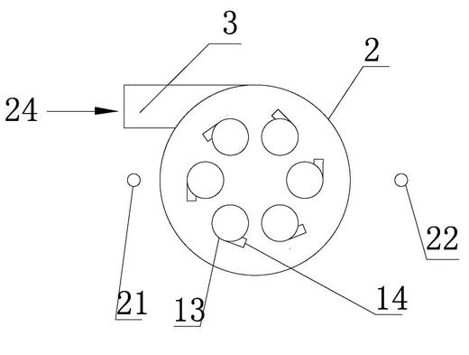
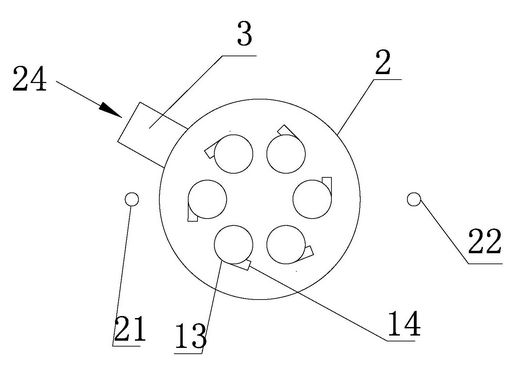
[0067] The gas-liquid separator 1 includes a housing 2, a gas-liquid inlet pipe 3 arranged on the upper side wall of the housing, an exhaust pipe 4 at the top of the housing, and a liquid discharge pipe 5 at the bottom of the housing. The foam breaking net 12, the cyclone 13, the riser pipe separator 18 and the upper foam breaking net 20, the inner space of the shell is divided into a liquid collection area 6 from bottom to top, a coalescing area 7 for the exhaust liquid and tail gas of the cyclone, and a cyclone separation Zone 8, riser separation zone 9 and riser exhaust tail liquid coalesc...

Embodiment approach 2

[0084] Figure 8 It is a schematic diagram of the overall structure of the gas-liquid separator scheme 2 of the present invention, which uses the gas-liquid separation process of the first-level cyclone separation, the second-level eddy current separation at the outlet of the gas riser, and the third-level coalescence separation of the foam breaking net to achieve complete gas-liquid separation;

[0085] The gas-liquid separator 1 includes a housing 2, a gas-liquid inlet pipe 3 arranged on the upper side wall of the housing, an exhaust pipe 4 at the top of the housing, and a liquid discharge pipe 5 at the bottom of the housing. The foam breaking net 12, the cyclone 13, the riser pipe separator 18 and the upper foam breaking net 20, the inner space of the shell is divided into a liquid collection area 6 from bottom to top, a coalescing area 7 for the exhaust liquid and tail gas of the cyclone, and a cyclone separation Zone 8, riser separation zone 9 and riser exhaust tail liqui...

Embodiment approach 3

[0098] Figure 10 It is a schematic diagram of the overall structure of the third scheme of the gas-liquid separator of the present invention. The gas-liquid separation process of the first-level cyclone separation, the second-level eddy current separation at the outlet of the gas riser, and the third-level coalescence separation of the foam breaking net is used to achieve complete gas-liquid separation. The inlets are directly connected with the inlets of each cyclone, without partitions;

[0099] The gas-liquid separator 1 includes a housing 2, a gas-liquid inlet pipe 3 arranged on the upper side wall of the housing, an exhaust pipe 4 at the top of the housing, and a liquid discharge pipe 5 at the bottom of the housing. The foam breaking net 12, the cyclone 13, the riser pipe separator 18 and the upper foam breaking net 20, the inner space of the shell is divided into a liquid collection area 6 from bottom to top, a coalescing area 7 for the exhaust liquid and tail gas of th...


PUM


Abstract

The invention relates to the technical field of petrochemical industry, especially to a gas-liquid separator for separating a gas phase flow from a liquid phase flow in a mixed gas-liquid flow. The space inside the shell of the gas-liquid separator is divided into a liquid collection zone (6), a cyclone apocenosis tail gas coalescence zone (7), a cyclone separation zone (8), an ascension pipe separation zone (9) and an ascension pipe exhaust tail liquid coalescence zone (10). A first-stage separation adopts cyclone separation; a second-stage separation adopts ascension pipe ejection separation or vortex separation; and a third-stage separation adopts a froth killer to further purify gases, so as to realize complete gas-liquid separation. The gas-liquid separator provided by the invention has a flexible structure and structure arrangement is optimized. More than two cyclone separators and the ascension pipe separator over the cyclone separators are integrated for the first-stage and second-stage separation. In the ascension pipe separation zone, exhaust momentum of the cyclone separators is utilized to strengthen the separation effect and realize the secondary separation process. The structure of the froth killer is improved so as to strengthen the separation effect as a whole.

Description

technical field [0001] The invention relates to the technical field of petrochemical industry, in particular to a gas-liquid separator for separating gas-phase flow and liquid-phase flow from mixed gas-liquid flow. Background technique [0002] Gas-liquid separation is a basic chemical process in petrochemical and other industries, which can realize the recovery of materials and the purification of target substances. The basic separation methods include gravity sedimentation, collision separation, centrifugal separation, Venturi gas-liquid separation, electric power Sedimentation, etc., are applicable to different particle size ranges; using different separation principles, the performance and structure of gas-liquid separators are also quite different, including split-free inertial separators, wire mesh gas-liquid separators, and separation tanks Separator, two-phase turbine separator, gravity sedimentation separator, parallel coil separator, cyclone separator, centrifugal ...

Claims


Application Information

Patent Timeline
Patent Type & Authority Applications(China)
IPC IPC(8): B01D50/00
Inventor 石宝珍
Owner QINGDAO JINGRUN PETROCHEM DESIGN INST CO LTD
Why Eureka
Try Eureka