Thermal bulging process for flash-welded stainless steel ring workpieces

A technology of flash welding and stainless steel, which is applied in the field of thermal expansion of stainless steel flash welding ring parts, can solve the problems of roundness and poor dimensional accuracy of flash welding ring parts, and achieve the effect of improving dimensional accuracy

Active Publication Date: 2012-06-13
GUIZHOU ANDA AVIATION FORGING
View PDF10 Cites 5 Cited by
  • Summary
  • Abstract
  • Description
  • Claims
  • Application Information

AI Technical Summary

Problems solved by technology

Since this method relies on the flexible contact between the liquid and the inner peripheral surface of the ring to cold expand the ring, its main function is to strengthen the ring. This method does not disclose in detail how to improve the dimensional accuracy of the ring through bulging, but only It is generally concluded that the purpose of improving the forming accuracy of the retaining ring can be achieved, that is, this method cannot solve the problems of the full circle and poor dimensional accuracy of the flash welding ring in the prior art

Method used


Image

  • Thermal bulging process for flash-welded stainless steel ring workpieces
  • Thermal bulging process for flash-welded stainless steel ring workpieces
  • Thermal bulging process for flash-welded stainless steel ring workpieces

Examples


specific Embodiment approach

[0042] The main chemical element content (percentage by weight) of the alloy is: C content ≤ 0.07%, Si content ≤ 1.00%, Mn content ≤ 1.00%, P content ≤ 0.035%, S content ≤ 0.025%, Cr content The content is 15.00%-17.50%, the Ni content is 3.00%-5.00%, the Cu content is 3.00%-5.00%, the Nb content is 0.15%-0.45%, and the balance is Fe.

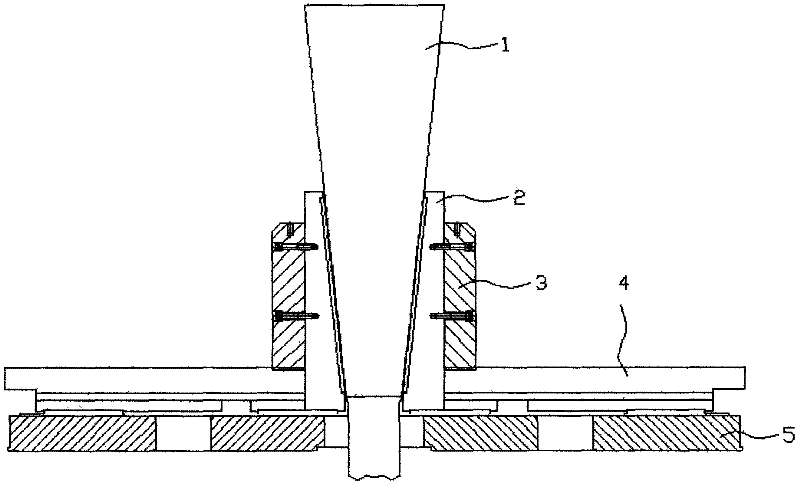
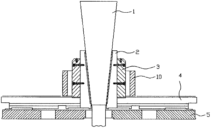
[0043] The structural diagram of the bulging machine for implementing the thermal bulging method of the present invention is as follows: figure 2As shown, the bulging machine is mainly composed of a mandrel slider 1, a radial slider 2, a bulging block 3, a workbench 4 and a guide rail 5. The mandrel slider 1 is conical and is set in the radial slider 2 to cooperate with the conical inner peripheral surface of the radial slider 2. The mandrel slider 1 can be driven by the hydraulic cylinder of the bulging machine on the radial slider 2. Move up and down in the axial direction and squeeze the radial slider 2; the radial slider 2 is installed on...


PUM

PropertyMeasurementUnit
sizeaaaaaaaaaa
thicknessaaaaaaaaaa
heightaaaaaaaaaa

Abstract

The invention discloses a thermal bulging process for flash-welded stainless steel ring workpieces, which includes steps of primary bulging; primary rotation; secondary rotation; secondary bulging and tertiary bulging. In the primary bulging, a flash-welded stainless steel ring workpiece which is annealed is sleeved on the periphery of a preheated bulging block in a bulging machine after being heated, and the bulging block squeezes the ring workpiece axially along the inner circumference of the ring workpiece after the bulging machine is started so that the primary bulging is completed, wherein the bulging temperature ranges from 950 DEG C to 1040 DEG C, the bulging time ranges from 22s to 28s, the pressure holding time ranges from 18s to 20s, and the bulging deflection ranges from 0.12% to 0.15%. The primary rotation is completed by rotating the ring workpiece along the center axis by 45 degrees. The secondary bulging is completed by processes of the primary bulging, wherein the bulging temperature ranges from 920 DEG C to 1010 DEG C, the bulging time ranges from 20s to 25s, the pressure holding time ranges from 16s to 18s, and the deflection ranges from 0.08% to 0.09%. The second rotation is completed by rotating the ring workpiece again along the direction the same with that of the primary rotation. The tertiary bulging is completed by the processes of the primary bulging again, wherein the bulging temperature ranges from 890 DEG C to 980 DEG C, the bulging time ranges from 25s to 30s, the pressure holding time ranges from 21s to 23s, and the deflection ranges from 0.09% to 1%. The dimensional precision of the ring workpiece can be 1%. to 2%. of the corresponding precision after the ring workpiece is bulged, and the ring workpiece is mainly used for the field of space navigation.

Description

technical field [0001] The invention relates to a bulging method for a ring, in particular to a thermal bulging method for a stainless steel flash welding ring. Background technique [0002] After the stainless steel flash welded ring is welded and formed, due to the influence of the welding process, the welded ring has a straight edge on its circumference, and the high stress of the ring after welding will cause the ring to warp and deform, resulting in its Formed into an irregular circular ring, its dimensional accuracy is poor. Generally, the welded ring can only be used after the full circle reaches the required size. [0003] The Chinese invention patent specification CN 101367104A published on February 18, 2009 discloses a hydraulic bulging strengthening process for replenishing fluid outside the retaining ring of a turbogenerator. Then inject the closed space formed by the fixed upper cone mold, the moving lower cone mold and the retaining ring through the passage in...

Claims


Application Information

Patent Timeline
Patent Type & Authority Applications(China)
IPC IPC(8): B21D31/04
Inventor 魏志坚杨勇蒲思洪张衡夏欲民黄锋邓远翔
Owner GUIZHOU ANDA AVIATION FORGING
Why Eureka
Try Eureka