
Process for producing graphite fluoride by low-temperature intercalation method

A technology of fluorinated graphite and intercalated graphite, applied in the chemical industry, can solve the problems of difficulty in large-scale production, danger, and relatively little research on the production process of fluorinated graphite, and achieve the effect of avoiding harsh requirements and avoiding danger.

Active Publication Date: 2012-06-13
江西高信前沿科技有限公司
View PDF3 Cites 5 Cited by
  • Summary
  • Abstract
  • Description
  • Claims
  • Application Information

AI Technical Summary

Problems solved by technology

[0002] The large-scale production of graphite fluoride, a high-tech product, is difficult. At the same time, due to the lack of corresponding application technology, there are relatively few researches on the production process of graphite fluoride; there are usually five production methods of graphite fluoride, which are Gas-phase method, solid-phase method, intercalation reaction method, fluorine plasma synthesis method, and carbon residue method, among which the yield of graphite fluoride by gas-phase method is about 20%, that of solid-phase method is about 15%, and that of plasma synthesis method is 10%. -30%, and the carbon residue method is about 10%. The yield of these methods is low and cannot be adapted to scale production; relatively speaking, the intercalation reaction method conforms to the characteristics of continuous scale production, and the product performance index is easy to control in the production process. By controlling the reaction time and temperature, fluorinated graphite with different fluorine-to-carbon ratios can be obtained. However, the current domestic production technology of fluorinated graphite is mainly based on the high-temperature method. The yield of fluorinated graphite is low, and the equipment requirements are high, which has certain risks. properties, and the fluorocarbon ratio of the produced fluorinated graphite is not high

Method used


Image

  • Process for producing graphite fluoride by low-temperature intercalation method
  • Process for producing graphite fluoride by low-temperature intercalation method

Examples


Embodiment 1

[0014] Example 1: The synthesis of graphite fluoride has three steps:

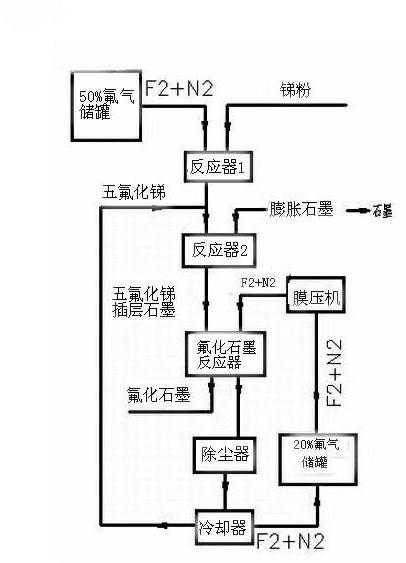
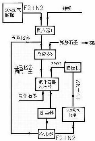
[0015] The production of graphite fluoride is divided into three steps: as figure 1 Shown:

[0016] In the first step, high-purity antimony pentafluoride is prepared by direct reaction of fluorine-nitrogen mixed gas with 50% mass percentage concentration of fluorine and nitrogen and antimony powder; the reaction equation is: 5F 2 +2Sb = 2SbF 5 .

[0017] Fluorine and nitrogen accounted for 50% of the mass percentage concentration of fluorine and nitrogen mixed gas, the flow rate is controlled by the fluorine gas flow meter, and enters the reactor from the reactor nozzle; The speed adjusts the feed amount; antimony powder and fluorine-nitrogen mixed gas directly react to generate gaseous antimony pentafluoride, and the gaseous antimony pentafluoride generated by the reaction is cooled by a cooler to obtain liquid high-purity antimony pentafluoride;

[0018] In the second step, liquid high-purity antim...


PUM


Abstract

The invention relates to a process for producing graphite fluoride by a low-temperature intercalation method. The process comprises the following steps of: using antimony pentafluoride intercalated graphite and a fluorine-nitrogen gas mixture to produce graphite fluoride, wherein the fluorine and the nitrogen in the fluorine-nitrogen gas mixture is respectively 10% -30% and 70% - 90 % by mass percentage concentration, the reaction temperature ranges from 200 DEG C to 500 DEG C, and the pressure ranges from 100KPa (Kilopascal) to 300KPa. Then, using the fluorine-nitrogen gas mixture with fluorine and nitrogen respectively of 50% by mass percentage concentration, and antimony powder to directly react for preparing gaseous antimony pentafluoride, and adding the liquid antimony pentafluoride acquired by cooling and expanded graphite to a vacuum container in a mass ratio of 1:1.5 to1:9, controlling the temperature to be 100 DEG C to 150 DEG C, and reacting for more than 12 hours to acquire the antimony pentafluoride intercalated graphite. The graphite fluoride yield can reach 43%- 74%, and the production is safe; simultaneously, the fluorine-to-carbon ratio of the graphite fluoride can be controlled by regulating the reaction time to acquire the graphite fluoride with different fluorine-to-carbon ratios.

Description

Technical field [0001] The present invention is a chemical industry, involving a process that produces fluorine graphic graphite under low temperature, low -pressure, and low -heavy process, and specially involves a process of producing fluoride graphic graphite in a low -temperature insertion method. Background technique [0002] The scale of the high -tech product itself of fluorophytte gifda is difficult to produce. At the same time, due to the lack of corresponding application technology, the production process of fluorine graphite is relatively small.Qi phase method, solid phase method, plug -in reaction method, fluorine plasma synthesis method, and residual carbon method, of which the yield of fluorophytic goblene is about 20%, the solid phase method is about 15%, the plasma synthesis method is 10 to 10— 30%, the residual carbon method is about 10%. The yield of these methods is low and cannot adapt to scale production. Relatively speaking, the intervening reaction method m...

Claims


Application Information

Patent Timeline
Patent Type & Authority Applications(China)
IPC IPC(8): C01B31/04C01B32/22
Inventor 刘鹏袁维金郭勇杨明柱孙飞
Owner 江西高信前沿科技有限公司
Learn More