Mechanical thermal cleaning method for pipe poles in oilfield wellhead sites

A technology for thermal cleaning and pipe rods, which is applied in the direction of cleaning equipment, earthwork drilling, wellbore/well components, etc. It can solve the problems of environmental pollution at the wellhead site, low heat energy utilization rate, shortening workover time, etc., and achieve shortening workover Time, convenient transportation, and the effect of saving transportation costs

Active Publication Date: 2014-09-03
洛阳水星天成石油设备有限公司
View PDF6 Cites 1 Cited by
  • Summary
  • Abstract
  • Description
  • Claims
  • Application Information

AI Technical Summary

Problems solved by technology

[0007] In order to solve the above problems, the present invention provides a method for mechanical thermal cleaning of pipes and rods at the wellhead of an oil field. Part of the machinery used in the method is based on "an automatic high-efficiency oil pipe thermal cleaning device", and in "an automatic On the basis of the "high-efficiency oil pipe thermal cleaning device", partial transformation and installation have been carried out to make it a pipe rod thermal cleaning device. The pipe rod thermal cleaning device can not only clean the oil pipe but also clean the sucker rod. Side entry and side exit, and finally equipped with auxiliary equipment around the pipe and rod thermal cleaning device, the pipe and rod thermal cleaning device and auxiliary equipment are arranged at the wellhead site of the oil field through a reasonable layout, and the pipe rod can be cleaned on the same machine at the wellhead site of the oil field Repairing saves the transportation cost of pipes and rods, improves the automation level of workover operations, and solves the problems of labor intensity, poor cleaning quality, low heat energy utilization rate, and serious environmental pollution at the wellhead site caused by manual cleaning of pipes and rods at the oilfield wellhead site. and other problems, shortening the workover time

Method used


Image

  • Mechanical thermal cleaning method for pipe poles in oilfield wellhead sites
  • Mechanical thermal cleaning method for pipe poles in oilfield wellhead sites

Examples


Embodiment Construction

[0045] The invention relates to a mechanical heat cleaning method for pipe rods at the wellhead site of an oil field.

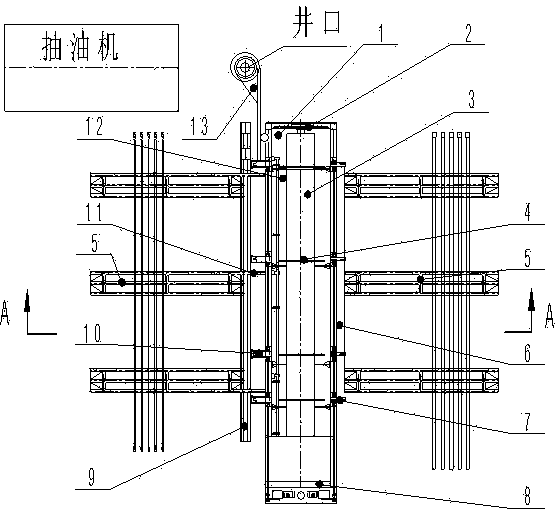
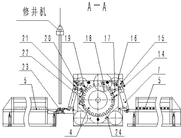
[0046] combine Figure 1-2 , the pipe and rod described in the mechanical heat cleaning method of the present invention refers to the oil pipe and the sucker rod, and the machinery described in the mechanical heat cleaning method includes a pipe and rod thermal cleaning device 1 and auxiliary equipment, wherein the pipe and rod thermal cleaning device 1 refers to The Chinese patent "An automatic high-efficiency oil pipe thermal cleaning device" has been partially modified and installed. To clean the sucker rod, secondly, the side entry and side exit of the pipe rod is realized. Auxiliary equipment is equipped around the pipe rod thermal cleaning device 1.

[0047] The conveying material rack 5 is composed of a material rack and a transition bridge 11. The material rack is welded by petroleum pipes. The conveying material rack 5 can be equipped with pipe stac...


PUM


Abstract

Disclosed is a mechanical thermal cleaning method for pipe poles in oilfield wellhead sites. The pipe poles are oil pipes and sucker rods. The mechanical thermal cleaning method is jointly realized by the aid of a pipe pole thermal cleaning device, auxiliary equipment, an oilfield wellhead site equipment overall arrangement mode and work procedures. The auxiliary equipment comprises a conveying rack, a retractable pipe gripping device and a conveying pulley, the oil pipes and the sucker rods can be cleaned by the same pipe pole thermal cleaning device, and side feed and side discharge of the pipe poles are realized. The pipe pole thermal cleaning device and the auxiliary equipment are reasonably arranged in an oilfield wellhead site, the pipe poles can be cleaned and repaired by the same machine in the oilfield wellhead site, conveying cost of the pipe poles is saved, automation level of workover treatment is improved, problems of high labor intensity of workers, poor cleaning quality, low thermal energy utilization rate, severe environmental pollution of the wellhead site and the like due to manual pipe pole cleaning in the oilfield wellhead site at present, and the like are resolved, and workover time is shortened.

Description

technical field [0001] The invention belongs to the technical field of cleaning oil well pipes and rods, in particular to a mechanical heat cleaning method for pipes and rods at the wellhead of an oil field. The pipes and rods mentioned in the method specifically refer to oil pipes and sucker rods. Background technique [0002] At present, the cleaning and repairing of oil pipes and sucker rods in major domestic oil fields is basically to pull the pipes and rods from the operation well site back to the pipe and rod repair base for cleaning, repair and reuse. The cost of transporting the pipes and rods back and forth is huge, especially for the ground The cost of transportation and cleaning of remote oil wells is even greater. For the convenience of description, the oil pipe and the sucker rod are combined and referred to as the pipe rod for short. The pipe rod includes both the oil pipe and the sucker rod. [0003] There are also examples of cleaning and repairing using the...

Claims


Application Information

Patent Timeline
Patent Type & Authority Patents(China)
IPC IPC(8): E21B37/00E21B36/00
Inventor 薛玉生孟昭焱卢非
Owner 洛阳水星天成石油设备有限公司
Why Eureka
Try Eureka