Supercharge Your Innovation With Domain-Expert AI Agents!

Shield tunneling machine for underground pipeline

A technology of underground pipelines and shield machines, which is applied in tunnels, mining equipment, earthwork drilling and mining, etc.

Active Publication Date: 2013-12-11
张英华
View PDF1 Cites 0 Cited by
  • Summary
  • Abstract
  • Description
  • Claims
  • Application Information

AI Technical Summary

Problems solved by technology

However, in the process of drilling and digging the hole and pushing the cement pipe into the hole, it will cause the dug hole to collapse.
Drilling holes and laying cement pipes must be completed in two steps, which is wasteful of work and time, and the construction cost is also high

Method used


Image

  • Shield tunneling machine for underground pipeline
  • Shield tunneling machine for underground pipeline
  • Shield tunneling machine for underground pipeline

Examples


Embodiment Construction

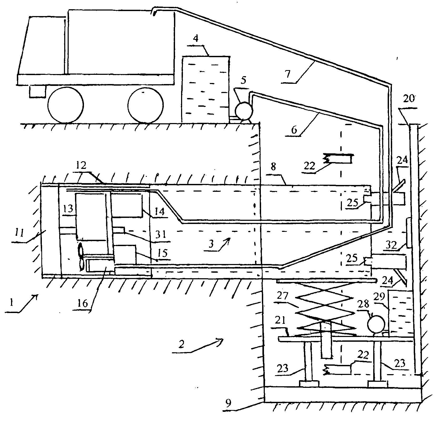
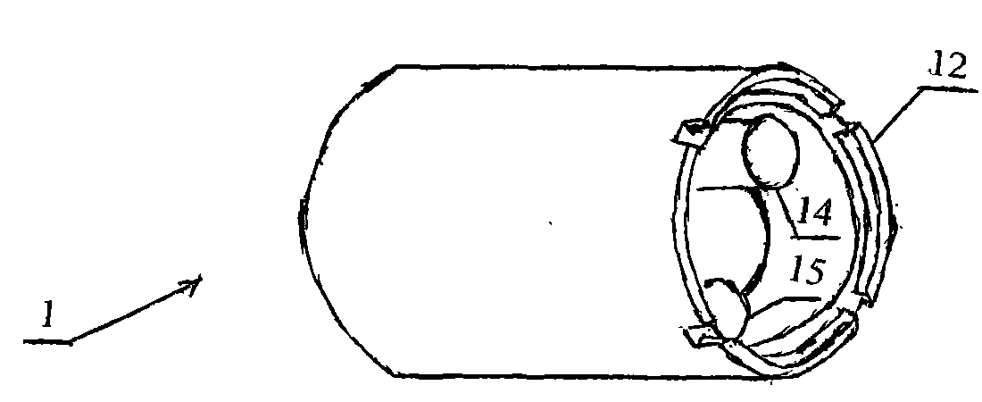
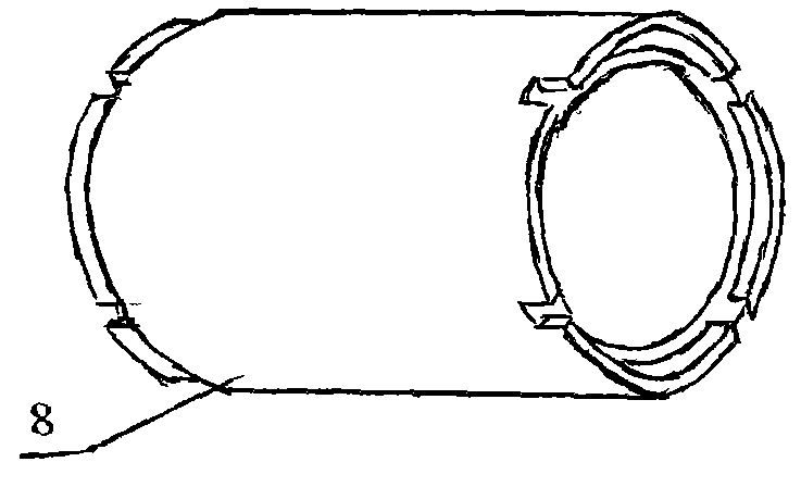
[0014] figure 1 , figure 2 , image 3 , Figure 4 and Figure 5As shown, the underground pipeline shield tunneling machine of the present invention is composed of a shield machine 1, a water pump 3, a water tank 5, a hydraulic propulsion device 2 and a computer control system. The shield machine 1 is composed of a cutter head 11 , a shield 12 , a motor 14 , a gear box 13 , a mixer 15 and a sludge pump 16 . The motor 14 drives the cutter head 11 to rotate after being decelerated by the gears of the gear box 13 . The water pump 4 outside the hole draws water from the water tank 5 and enters the shield machine 1 through the water pipe 6 to spray to the upper part of the cutter head 11 to cool the cutter head 11 and flush the sludge on the cutter head 11. The mixer 15 stirs the sludge evenly, crushes the stones, and scrapes off the large sandstones on the filter screen at the inlet of the sludge pump 16. Sludge pump 16 is contained in the below of gear box 13, and sludge p...


PUM


Abstract

The invention discloses a shield tunneling machine for paving an underground pipeline. A round manhole pit is dug, and a hydraulic propulsion device is arranged into the manhole pit. The shield tunneling machine is placed on a hydraulic lifting platform to be descended to the lowest position. A hydraulic jack abuts against the tail portion of the shield tunneling machine. Hydraulic legs are adjusted to enable a cutter head of the shield tunneling machine to align at a drilling-digging position. Hydraulic positioning hands are inserted into the side wall of the manhole pit to position the hydraulic propulsion device. The hydraulic jack extends to push the shield tunneling machine to move forward. A motor decelerates through a gear box to drive the cutter head to rotate. A water pump pumps water from a water tank, and the water enters the shield tunneling machine to be sprayed onto the upper portion of the cutter head. A sludge pump pumps sludge mixed by a mixer onto an automobile through a sludge pipe. The hydraulic jack retracts after drilling and digging to a certain depth, a cement pipe is placed on the hydraulic lifting platform, and a cement pipe connecting plug is inserted into a socket at the tail portion of the shield tunneling machine. The hydraulic jack pushes the cement pipe and the shield tunneling machine to move, and the shield tunneling machine continues to drill and dig. Therefore, users can directly pave the underground cement pipe without excavating a groove.

Description

Technical field: [0001] The invention relates to an underground pipeline shield tunneling machine. Background technique: [0002] At present, the laying of underground sewage pipes all is to dig a deep groove with a hook machine first, put down the joint cement pipes after laying a layer of concrete at the bottom of the groove, and connect the joint cement pipes with cement; Bury it, and lay a layer of concrete or tiles on top. Laying underground sewer pipes like this will cause traffic jams in busy areas and also damage road surfaces. Application number CN201110030571.6 "Self-propelled Miniature Underground Pipeline Tunneling Machine", it can drill obliquely from the ground to the ground, then drill horizontally to dig out a hole with a smaller diameter, and then push the cement pipe into the hole. However, in the process of drilling and digging the hole and pushing the cement pipe into the hole, it will cause the dug hole to collapse. Drilling and laying cement pipes w...

Claims


Application Information

Patent Timeline
Patent Type & Authority Patents(China)
IPC IPC(8): E21D9/08
Inventor 张英华
Owner 张英华
Features
  • R&D
  • Intellectual Property
  • Life Sciences
  • Materials
  • Tech Scout
  • Unparalleled Data Quality
  • Higher Quality Content
  • 60% Fewer Hallucinations
Learn More