
Energy-saving control system, truck crane and energy-saving control method

An energy-saving control system and controller technology, which is applied in the control system, pump control, AC motor control, etc., can solve the problems of uncontrollable torque, engine flameout, and complicated speed selection, so as to protect pipelines and solenoid valves, Improve energy saving efficiency and reduce the effect of unloading flow

Active Publication Date: 2012-06-13
SANY AUTOMOBILE HOISTING MACHINERY
View PDF4 Cites 13 Cited by
  • Summary
  • Abstract
  • Description
  • Claims
  • Application Information

AI Technical Summary

Problems solved by technology

[0002] At present, in the hydraulic pump system driven by the electric motor, the speed of the electric motor is mainly adjusted through the frequency adjustment pedal, the energy saving efficiency is not very high, and at the same time, it cannot ensure sufficient torque and protect the hydraulic system well; while it is driven by a diesel engine In the hydraulic pump system, the engine speed and the displacement of the hydraulic pump are mainly adjusted by the controller. The speed adjustment accuracy is not high. At the same time, the speed selection method is complicated, and the fuel consumption of the engine will also change with its cumulative working time.
[0003] related technologies, such as figure 1 The energy-saving control system shown uses the controller to adjust the engine speed and the displacement of the hydraulic pump. With this energy-saving method, the engine speed adjustment accuracy is not high, and the torque cannot be controlled, which may cause the engine to stall due to insufficient torque. ;The speed selection method is complicated; the fuel consumption of the engine will fluctuate with the cumulative running time of the engine, and the best fuel consumption point cannot be corrected

Method used


Image

  • Energy-saving control system, truck crane and energy-saving control method
  • Energy-saving control system, truck crane and energy-saving control method
  • Energy-saving control system, truck crane and energy-saving control method

Examples


Embodiment Construction

[0026] In order to understand the above-mentioned purpose, features and advantages of the present invention more clearly, the present invention will be further described in detail below in conjunction with the accompanying drawings and specific embodiments.

[0027] In the following description, many specific details are set forth in order to fully understand the present invention, but the present invention can also be implemented in other ways different from those described here, therefore, the present invention is not limited to the specific embodiments disclosed below limit.

[0028]In order to make those skilled in the art better understand the technical solution according to the present invention, an example of the energy-saving control system according to the present invention will be described below.

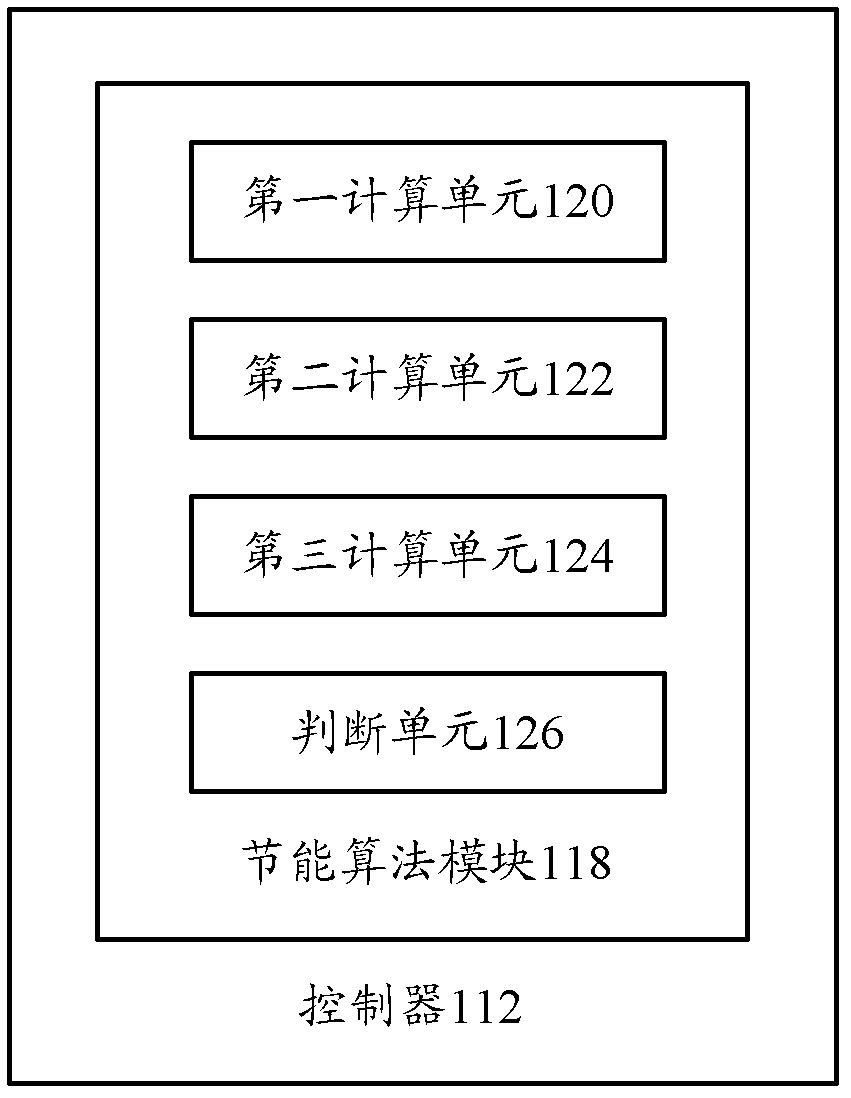
[0029] figure 2 A schematic diagram of an energy saving control system according to an embodiment of the present invention is shown.

[0030] Such as figure 2 As sho...


PUM


Abstract

The invention provides an energy-saving control system. The energy-saving control system comprises an operating device, a pressure sensor, a frequency converter, a controller and a variable displacement pump, wherein the operating device is used for transmitting the flow required by the variable displacement pump to the controller; the pressure sensor senses a load pressure signal of an actuating mechanism and transmits the load pressure signal to the controller; the frequency converter feeds back a current rotating speed signal and a current torque signal of a motor to the controller so as to adjust the rotating speed and the torque of the motor according to a first adjusting command; the controller is connected to the frequency converter, the variable displacement pump and the pressure sensor, calculates an initial rotating speed value and an initial torque value of the motor and a displacement value of the variable displacement pump according to the required flow, the current rotating speed signal, the current torque signal and the load pressure signal, generates the first adjusting command and sends the first adjusting command to the frequency converter, and generates a second adjusting command and sends the second adjusting command to the variable displacement pump; and the variable displacement pump adjusts the displacement according to the second adjusting command. The high-efficiency combined control over the rotating speed and the torque of the motor and the displacement of the variable displacement pump starting from a required variable, namely the single variable of the variable displacement pump is realized.

Description

technical field [0001] The invention relates to an energy-saving control system, in particular to an energy-saving control system, a truck crane and an energy-saving control method. Background technique [0002] At present, in the electric motor-driven hydraulic pump system, the speed of the motor is mainly adjusted through the frequency adjustment pedal, the energy-saving efficiency is not very high, and at the same time, it cannot ensure sufficient torque and protect the hydraulic system well; while the hydraulic pump driven by a diesel engine In the hydraulic pump system, the engine speed and the displacement of the hydraulic pump are mainly adjusted by the controller. The speed adjustment accuracy is not high. At the same time, the speed selection method is complicated, and the fuel consumption of the engine will also change with its cumulative working time. [0003] related technologies, such as figure 1 The energy-saving control system shown uses the controller to adj...

Claims


Application Information

Patent Timeline
Patent Type & Authority Applications(China)
IPC IPC(8): F04B49/06H02P27/04
Inventor 朱湘华周斌赵荣国
Owner SANY AUTOMOBILE HOISTING MACHINERY
Learn More