Check patentability & draft patents in minutes with Patsnap Eureka AI!

Fault detection circuit and method

A fault detection circuit and fault detection technology, applied in the field of power supply, can solve problems such as the limitation of circuit working efficiency, achieve the effect of reducing quiescent current and improving working efficiency

Active Publication Date: 2012-06-13
CHENGDU MONOLITHIC POWER SYST
View PDF3 Cites 9 Cited by
  • Summary
  • Abstract
  • Description
  • Claims
  • Application Information

AI Technical Summary

Problems solved by technology

However, the quiescent current cannot be reduced without limit, so that the improvement of circuit operating efficiency is limited

Method used


Image

  • Fault detection circuit and method
  • Fault detection circuit and method
  • Fault detection circuit and method

Examples


Embodiment Construction

[0015] The fault detection circuit of the embodiment of the present invention will be described in detail below. In the following description, some specific details, such as specific circuit structures in the embodiments and specific parameters of these circuit elements, are used to provide a better understanding of the embodiments of the present invention. It will be understood by those skilled in the art that embodiments of the invention may be practiced even without some details or other combinations of methods, elements, materials, and the like.

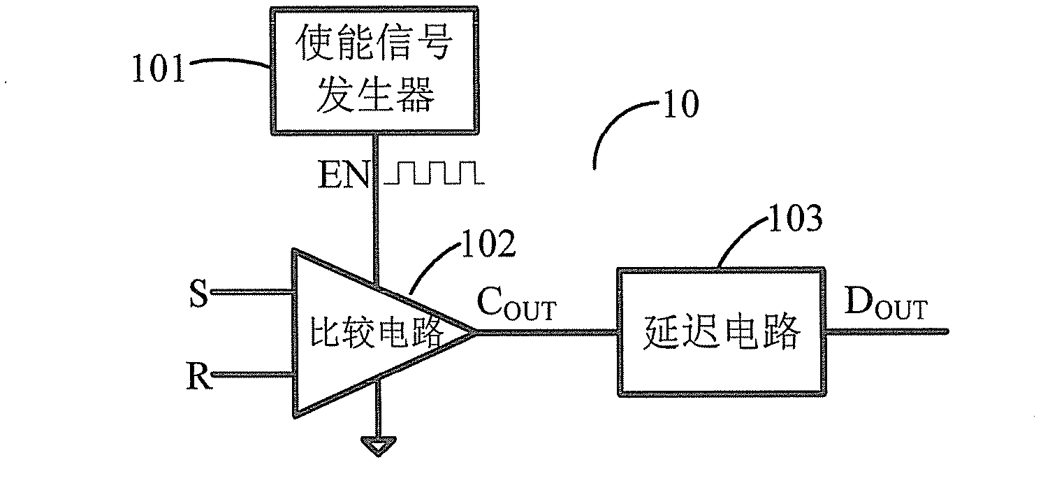
[0016] figure 1 A fault detection circuit 10 according to an embodiment of the present invention is schematically shown. like figure 1 As shown, the fault detection circuit 10 includes an enable signal generator 101 , a comparison circuit 102 and a delay circuit 103 .

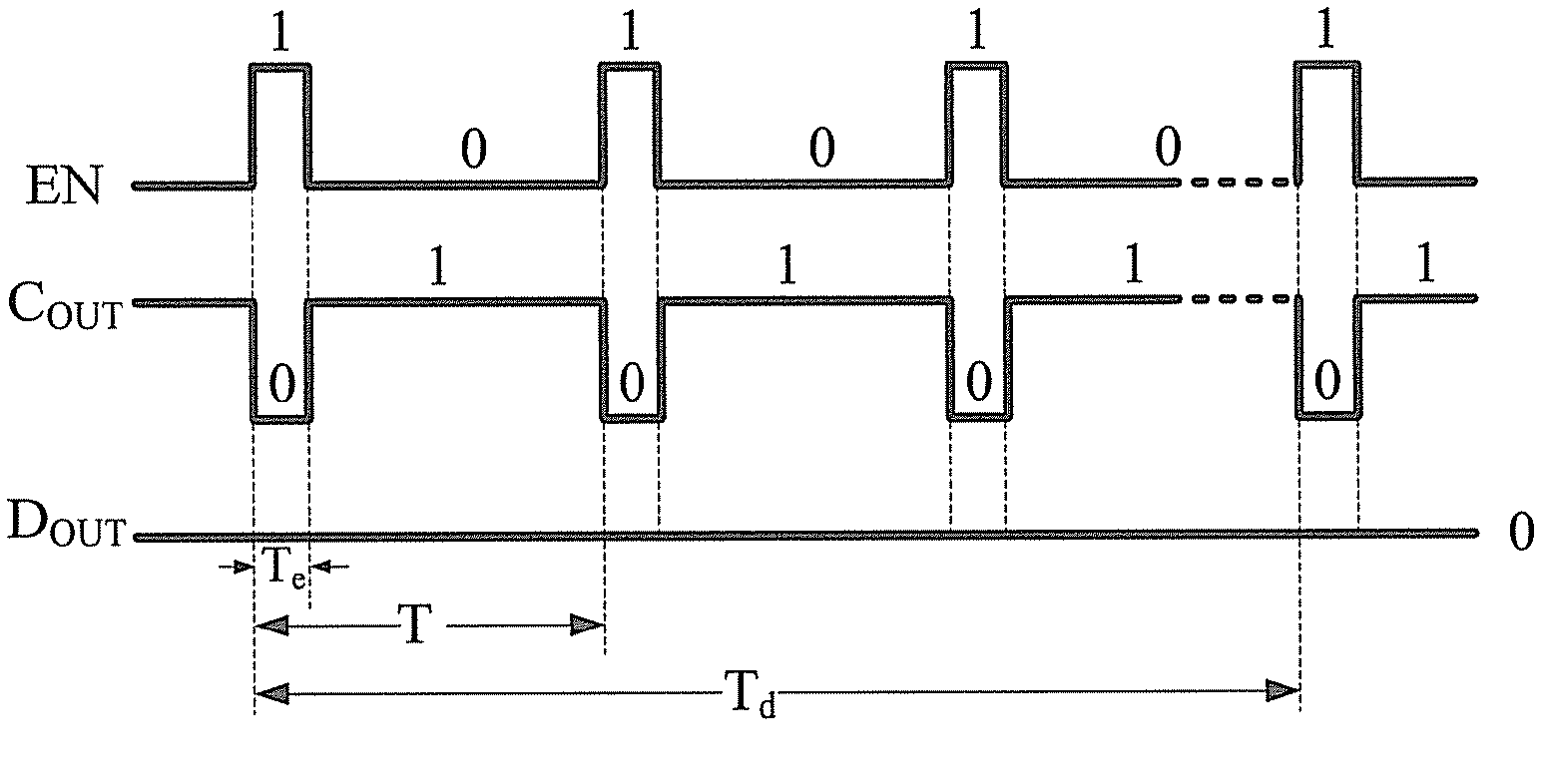
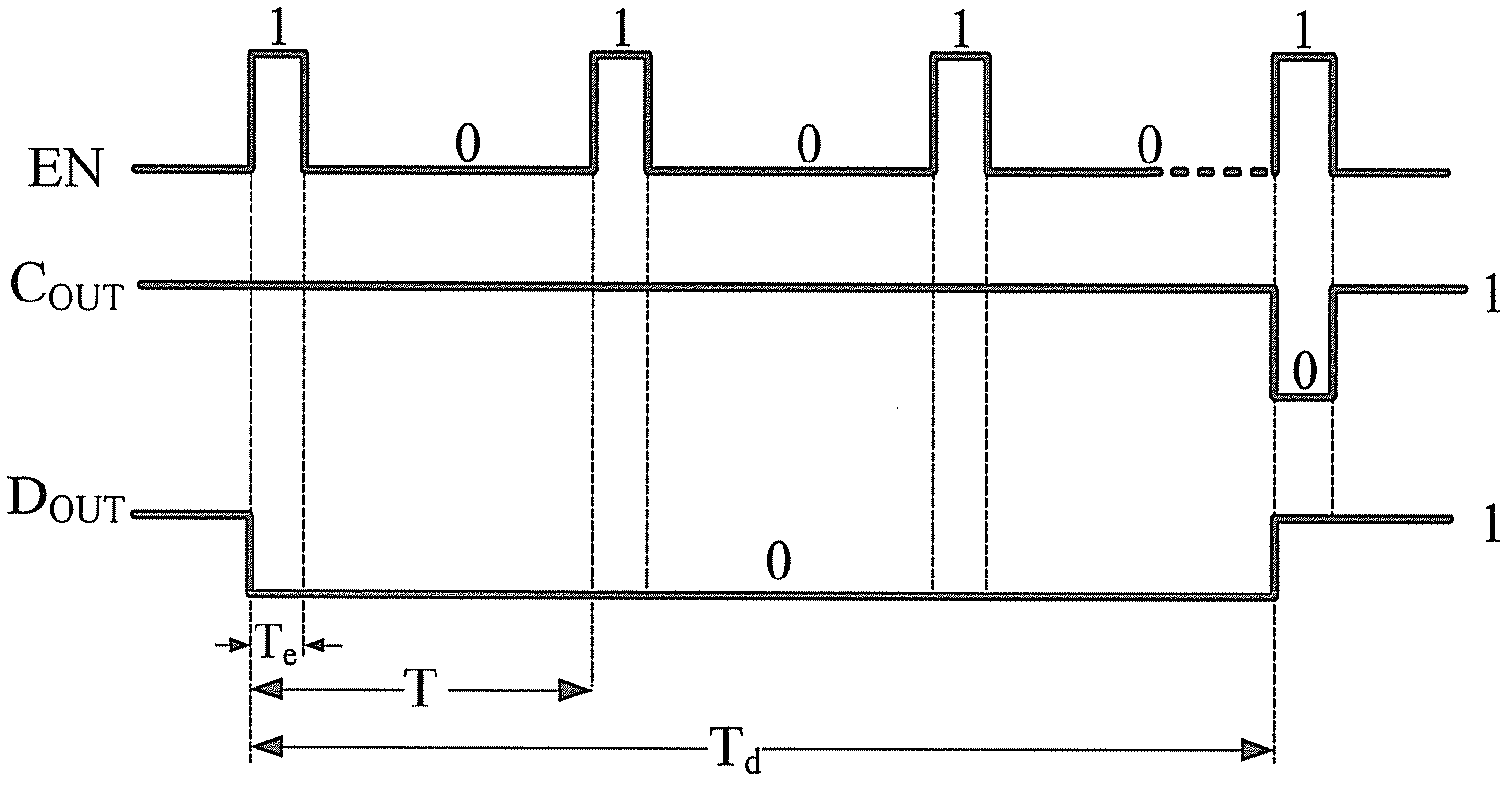
[0017] The enable signal generator 101 generates the enable signal EN, wherein the enable signal EN is a square wave signal with a period of T, which is at T ...


PUM


Abstract

The invention discloses a fault detection circuit and a detection method. The fault detection circuit comprises an enable signal generator, a comparison circuit and a delay circuit, wherein the enable signal generator is used for generating a periodic enable signal; the comparison circuit is used for comparing an enable signal received by an enable terminal with an output signal of a protected circuit and a reference signal received by an input terminal, and outputting a comparison result signal; and the delay circuit is used for receiving the comparison result signal, detecting the value of the comparison result signal within a set time period, and outputting a delay signal according to a detection result, wherein the set time is longer than the period of the enable signal. By adoption of the embodiment provided by the invention, the quiescent current consumption can be reduced, and the circuit working efficiency is improved.

Description

technical field [0001] Embodiments of the present invention relate to the field of power supplies, and more specifically, embodiments of the present invention relate to a fault detection circuit and a method thereof. Background technique [0002] In switching regulator circuits, battery-powered circuits and other applications, circuit protection, such as overvoltage, overcurrent or overtemperature protection, is a key technology. In the prior art, the control chip is used to monitor the voltage, current, temperature or other parameters of the circuit to be protected, and to protect it. Since the control chip needs to consume static current, the control chip directly affects the working efficiency of the protected circuit. [0003] In the prior art, in order to improve the working efficiency of the circuit, the quiescent current is usually reduced. However, the quiescent current cannot be reduced without limit, so that the improvement of the working efficiency of the circui...

Claims


Application Information

Patent Timeline
IPC IPC(8): G01R31/28G01R19/165
CPCG01R31/00H03H11/265H03K5/19G01R31/31721
Inventor 周江云李佚珂
Owner CHENGDU MONOLITHIC POWER SYST
Features
  • R&D
  • Intellectual Property
  • Life Sciences
  • Materials
  • Tech Scout
  • Unparalleled Data Quality
  • Higher Quality Content
  • 60% Fewer Hallucinations
Learn More