Manufacturing method of solar battery module and solar battery module

A technology of solar cells and solar cells, which is applied in the direction of electrical components, chemical instruments and methods, circuits, etc., can solve the problems of inability to process curved solar cell components, expensive solar cell component equipment, and inability to process solar cell components. Uniform die stress distribution, low cost and high yield

Active Publication Date: 2012-06-13
CHERY AUTOMOBILE CO LTD
View PDF6 Cites 6 Cited by
  • Summary
  • Abstract
  • Description
  • Claims
  • Application Information

AI Technical Summary

Problems solved by technology

In this process, the laminator needs to be evacuated, and after heating, cooling and other processes, the processing time of a single solar module is as long as ten minutes, and the operation time is long and the efficiency is low.
Moreover, since the existing thermal lamination process requires the use of professional processing equipment and molds, there are still problems such as expensive equipment and complicated processes in the production process of solar cell modules
[0003] In addition, the solar cell modules processed by the above-mentioned process will be limited by the lamination shape and size of the laminator, so the processed solar modules are basically They are all planar photovoltaic components, but cannot process curved solar cell components; and there is also a limit to the size of the processed solar components, therefore, this process cannot process large-area solar cell components

Method used


Image

  • Manufacturing method of solar battery module and solar battery module
  • Manufacturing method of solar battery module and solar battery module
  • Manufacturing method of solar battery module and solar battery module

Examples


Embodiment 1

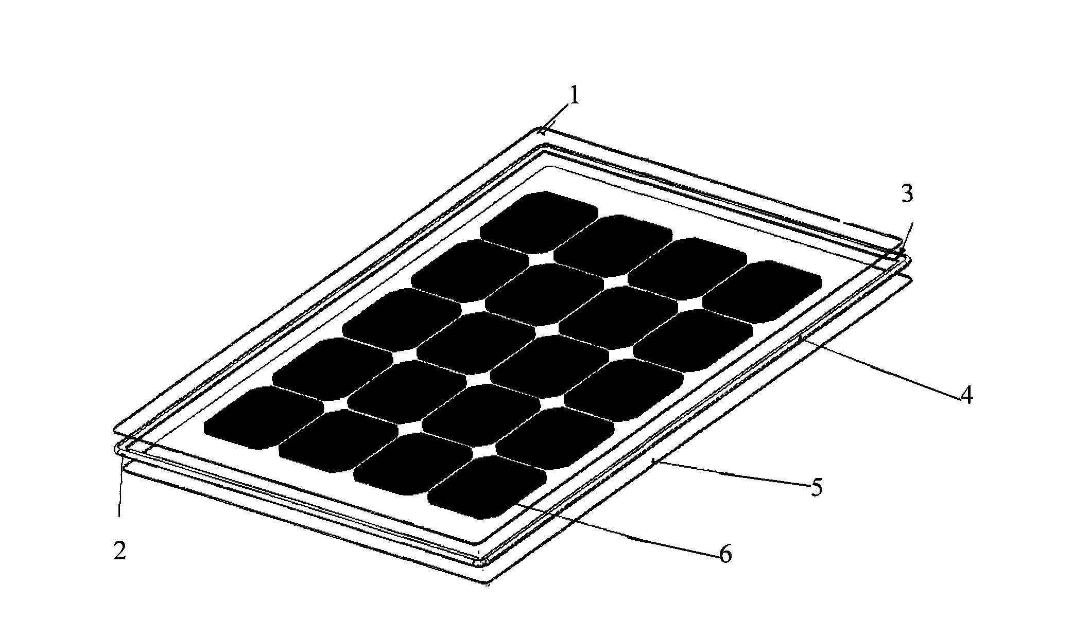
[0050] Such as figure 2 , 3 As shown, the solar cell components produced in this embodiment are planar solar cell components.

[0051] Such as figure 1 As shown, the specific steps of the manufacturing method of the planar solar cell module are as follows:

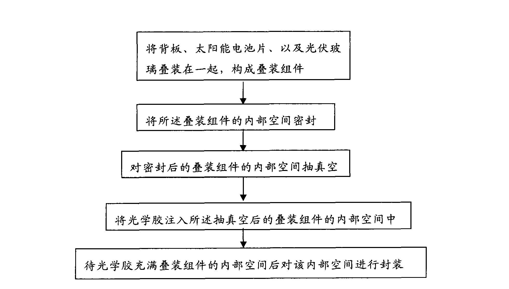
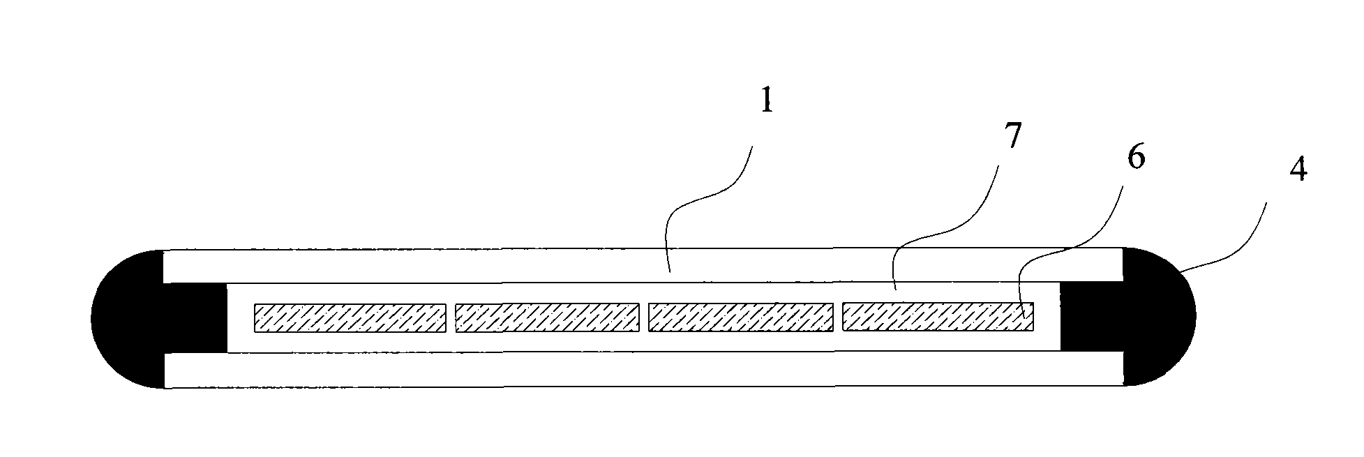
[0052] 1) After the photovoltaic glass 1 is cleaned, the back plate 5, a plurality of solar cells 6 connected in series, and the photovoltaic glass 1 are stacked to assemble a stacked assembly, wherein the solar cells 6 are in the Between the back plate 5 and the photovoltaic glass 1 in the stacked assembly, that is, in the internal space of the stacked assembly;

[0053] 2) A sealing strip 4 is provided at the edge of the internal space of the stacked assembly to seal the internal space, and a glue inlet 2 and a glue outlet 3 are provided on the sealing strip 4;

[0054] 3) Connect the glue outlet 3 to an external vacuum pump, seal the glue inlet 2 with a rubber clip, and turn on the vacuum pump connected to the glue...

Embodiment 2

[0065] Such as Figure 4 , 5 As shown, the solar cell assembly produced in this embodiment is a curved solar cell assembly.

[0066] The difference between the manufacturing method of the solar cell module in this embodiment and the manufacturing method in Embodiment 1 is: in step 2), after sealing the inner space of the stacked module with the sealing tape 4, and then sealing the The two ends of the above-mentioned stacked assembly are respectively fixed on the slots 8 of the manufacturing tool, and then the soft film 9 is installed on the back plate 5 . The soft film 9 forms a sealed space in the curved solar cell assembly, and can adapt to the shape of the curved surface assembly, allowing optical glue to be injected to form the curved surface solar assembly.

[0067] Since the shape of the solar cell module in this embodiment is a curved surface, it cannot be directly placed on a horizontal surface for processing, so it is placed on the tooling slot 8 to facilitate subse...


PUM

PropertyMeasurementUnit
thicknessaaaaaaaaaa

Abstract

The invention provides a manufacturing method of a solar battery module. The method comprises the following steps: stacking a backboard, a solar battery sheet and photovoltaic glass together to form a stack assembly; (2) sealing internal space of the stack assembly; (3) carrying out vacuum-pumping on the sealed internal space of the stack assembly; (4) injecting optical cement into the internal space of the stack assembly after vacuum-pumping processing; and (5) after filling out the internal space of the stack assembly with the optical cement, sealing the internal space. Correspondingly, the invention provides a solar battery module prepared by employing the above method. The manufacturing method of the invention is simple in technology, operation time can be substantially shortened, and product yield is high.

Description

technical field [0001] The invention relates to a manufacturing method of a solar battery module and a solar battery module made by the manufacturing method. Background technique [0002] At present, solar cell modules are mostly made of thermal lamination process through lamination machine: the thermal packaging material EVA (ethylene-vinyl acetate copolymer, namely ethylene-vinyl acetate copolymer) is melted under vacuum conditions and then wrapped Around the solar cells, the purpose of protecting the solar cells from external damage is achieved. In this process, the laminator needs to be evacuated, and after heating and cooling processes, the processing time of a single solar module is as long as ten minutes, and the operation time is long and the efficiency is low. Moreover, since the existing thermal lamination process requires the use of professional processing equipment and molds, there are still problems such as expensive equipment and complicated processes in the p...

Claims


Application Information

Patent Timeline
Patent Type & Authority Applications(China)
IPC IPC(8): H01L31/18H01L31/048B32B37/12
CPCY02E10/50Y02P70/50
Inventor 严伟卢磊焦芳芳王秀田
Owner CHERY AUTOMOBILE CO LTD
Why Eureka
Try Eureka