
Atmospheric pressure optical plasma brush-type device and electric discharge method thereof

A plasma brush and atmospheric pressure technology, applied in the field of plasma, can solve problems such as unseen applications, and achieve the effects of controllable discharge area, simple discharge method, and low cost of discharge equipment

Inactive Publication Date: 2014-03-12
东丰科林(天津)医疗科技有限公司
View PDF6 Cites 0 Cited by
  • Summary
  • Abstract
  • Description
  • Claims
  • Application Information

AI Technical Summary

Problems solved by technology

[0002] In recent years, with the development of plasma technology, atmospheric pressure discharge has been widely used in various fields, but there is no application or report on the technology of generating controllable area uniform and dense plasma by means of optical fiber tube discharge under atmospheric pressure in the world.

Method used


Image

  • Atmospheric pressure optical plasma brush-type device and electric discharge method thereof
  • Atmospheric pressure optical plasma brush-type device and electric discharge method thereof
  • Atmospheric pressure optical plasma brush-type device and electric discharge method thereof

Examples


Embodiment 1

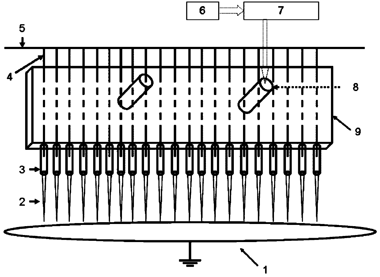
[0029] Atmospheric pressure fiber optic plasma brush devices, such as figure 1 As shown, it includes a high-voltage AC power supply 5, an air cavity 9, a group of microporous optical fibers 3 and corresponding high-voltage electrodes 4 and a ground electrode 1;

[0030] The high-voltage electrode 5 is connected to a high-voltage AC power supply 5, and a high-voltage electrode 5 is correspondingly inserted into a microporous optical fiber 3;

[0031] The micro-hole optical fiber 3 is evenly arranged in parallel and fixed in the air cavity 9; the air cavity 9 is provided with a small hole matching the outer diameter of the optical fiber corresponding to the discharge end of the micro-hole optical fiber 3;

[0032] Described microhole optical fiber 3 has through hole, and its outer diameter is 1mm, and inner diameter is 50 μ m; The discharge end of microhole optical fiber 3 passes outside the air cavity 9 through the aperture of described air cavity; The quantity of microhole opt...

Embodiment 2

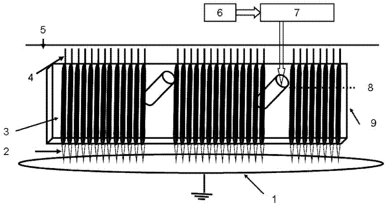
[0039] Another atmospheric-pressure fiber optic plasma brush device, such as image 3 As shown, it is different from Embodiment 1 in that the microhole fiber 3 has a blind hole, that is, its discharge end is closed, then the microhole fiber 3 is placed in the air cavity 9, and its discharge end is in the air cavity 9. The air cavity is close to the small hole in the air cavity; the power supply 5 is turned on for a period of time, and the gas passes through the outer surface of the optical fiber 3 with blind holes, and discharges at its closed end; thereby generating a uniform and dense atmospheric pressure plasma with a controllable area Body 2.


PUM


Abstract

The invention relates an atmospheric pressure optical plasma brush-type device and an electric discharge method thereof. The device comprises an alternating current power supply, an air cavity, microporous optical fibers, high voltage electrodes and a ground electrode, wherein the high voltage electrodes are correspondingly inserted into the microporous optical fibers. According to the invention, the microporous optical fibers are uniformly arranged, the inner parts or the outer parts of the microporous optical fibers are communicated with air, electricity can be discharged under an atmospheric pressure condition, thus plasmas can be generated at electric discharge ends of the microporous optical fibers, and the plasmas can be used for carrying out material surface modification and the processing for materials, cancel cells, bacterium and the like in biomedicine. The atmospheric pressure optical plasma brush-type device disclosed by the invention has the advantages that the cost of an electric discharge device is low, the size is small, the electric discharge mode is simple, a low-voltage vacuum environment is not needed, the energy consumption is low, the electric discharge is stable, uniform and compact, the electric discharge area is controllable, and the electric discharge duration is unlimited.

Description

technical field [0001] The invention relates to the technology of utilizing dielectric barrier discharge plasma under atmospheric pressure, in particular to a device, method and application for generating controllable area, uniform and dense atmospheric pressure plasma by means of an optical fiber tube. Background technique [0002] In recent years, with the development of plasma technology, atmospheric pressure discharge has been widely used in various fields, but there is no application or report on the technology of generating controllable area uniform and dense plasma by means of optical fiber tube discharge under atmospheric pressure in the world. . Contents of the invention [0003] In view of the needs of the prior art, the present invention aims to provide a device and method for generating large-scale uniform and dense plasma by using an optical fiber tube and discharging under atmospheric pressure, which has the advantages of simple structure, energy saving and l...

Claims


Application Information

Patent Timeline
Patent Type & Authority Patents(China)
IPC IPC(8): H05H1/24
Inventor 刘东平倪维元
Owner 东丰科林(天津)医疗科技有限公司
Learn More