
Multi-start worm milling machine

A multi-head worm and milling machine technology, applied in the direction of worms, gear teeth, gear cutting machines, etc., can solve the problems of low indexing accuracy, low processing pass rate, and inability to process, so as to achieve improved indexing accuracy, high transmission accuracy, and indexing accuracy. high precision effect

Active Publication Date: 2012-06-20
NANJING CAIYUN MASCH & ELECTRONICAL MFG GRP CO LTD
View PDF6 Cites 18 Cited by
  • Summary
  • Abstract
  • Description
  • Claims
  • Application Information

AI Technical Summary

Problems solved by technology

[0003] After processing one thread on the worm, the rotation of the main shaft drives the worm to rotate at a certain angle (ie, indexing) to process another thread, because the main shaft box adopts an ordinary belt gear transmission mechanism composed of spur gears and helical gears. The precision angle, so the indexing accuracy is low, the indexing deviation is large, the general deviation is 7-10″ (seconds)
[0004] In addition, when the existing milling machine is processing a directly smaller thin worm, although the head end of the worm is clamped by the chuck on the main shaft, because the tail end of the worm is too thin, it cannot be pushed by a thimble. The bending is relatively large, resulting in a low processing pass rate, and even cannot be processed in severe cases

Method used


Image

  • Multi-start worm milling machine
  • Multi-start worm milling machine
  • Multi-start worm milling machine

Examples


Embodiment Construction

[0016] The present technology will be further described below through embodiments in conjunction with the accompanying drawings.

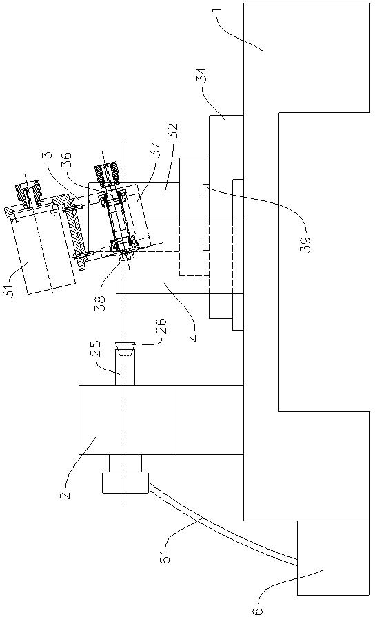
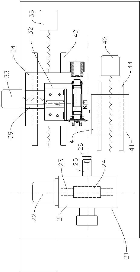
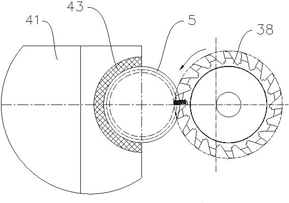
[0017] The multi-head worm milling machine includes a machine base 1, a headstock 2 for driving the machined worm to rotate, a cyclone milling head 3 including a milling cutter, and a tailstock device 4 for milling the machined worm.

[0018] The main shaft box 2 includes a box body 21 , a main servo motor 22 , a main worm 23 , a main turbine 24 that cooperates with the main worm 23 , a main shaft 25 , and the like. The output shaft of the main servo motor is connected with the main worm, and the main turbine shaft 26 is connected with the main shaft. The rotation of the main servo motor 22 drives the main worm 23 to rotate, and the main turbine 24 drives the main shaft 25 to rotate. An elastic jacket 26 is provided on the main shaft 25, and the elastic jacket is powered by an oil cylinder for clamping the head end of the worm.

[0019] The tails...


PUM


Abstract

The technology provides a multi-start worm milling machine with high indexing accuracy. The multi-start worm milling machine comprises a base, a main shaft box and a cyclone milling head, wherein the main shaft box is used for driving a processed worm to rotate, the cyclone milling head is used for milling the processed worm and comprises a milling cutter, the main shaft box comprises a box body, a main shaft actuating mechanism, a main shaft transmission mechanism and a main shaft, the main shaft actuating mechanism drives the main shaft to rotate through the main shaft transmission mechanism, the main shaft actuating mechanism is a main servo motor, and the main shaft transmission mechanism adopts a worm gear for transmission.

Description

technical field [0001] The present technology relates to a multi-head worm milling machine. Background technique [0002] The existing milling machine for milling multi-head worms includes a machine base, a headstock for driving the worm to be processed, and a whirlwind milling head including a milling cutter for milling the worm to be processed. The headstock includes a box Body, main motor, belt gear transmission mechanism composed of pulley, spur gear, helical gear, etc., main shaft, the main motor drives the main shaft to rotate through the belt gear transmission mechanism. [0003] After processing a thread on the worm, the worm is rotated by the main shaft to rotate a certain angle (ie, indexing) to process another thread, because the main shaft box adopts an ordinary belt gear transmission mechanism composed of spur gears, helical gears, etc. Therefore, the indexing accuracy is low, and the deviation of the indexing is large, and the general deviation is 7-10″ (secon...

Claims


Application Information

Patent Timeline
IPC IPC(8): B23F13/00B23F23/08B23F23/00
Inventor 孙秋云
Owner NANJING CAIYUN MASCH & ELECTRONICAL MFG GRP CO LTD
Learn More