Equipment for automatically welding vacuum corrugated pipe

A technology of automatic welding and bellows, which is applied in welding equipment, metal processing equipment, auxiliary equipment, etc., can solve the problems of uncontrollable weld quality, low welding precision, and low degree of automation, and achieve easy maintenance and improvement, and convenient welding Precise, yield-enhancing effects

Inactive Publication Date: 2012-06-20
CHINA JILIANG UNIV
View PDF8 Cites 5 Cited by
  • Summary
  • Abstract
  • Description
  • Claims
  • Application Information

AI Technical Summary

Problems solved by technology

The current bellows welding methods are all manual welding: fill the bellows rotating tooling with bellows to be welded, cover with a glass sealing cover, vacuumize with a vacuum pump, start to manually rotate the bellows welding tooling, and weld several bellows in turn When finished, take off the glass sealing cover; during the welding process, the size of the weld cannot be accurately observed, and the feeding amount of the electrode cannot be accurately adjusted according to the size of the weld. It can only be fed by experience, and the quality of the weld cannot be controlled. Welding quality and welding speed are greatly affected by the operator's technical level and work mood
Furthermore, manual bellows welding has disadvantages such as low equipment automation, unreasonable test methods, low welding accuracy, poor consistency, cumbersome operation, time-consuming and inefficient, etc. Therefore, it is necessary to design and develop bellows that are easy to weld, accurate in welding, and fast in operation. Automatic welding equipment, processes and methods meet the needs of corrugated pipe manufacturers and are an effective way to improve the quality of corrugated pipes

Method used


Image

  • Equipment for automatically welding vacuum corrugated pipe
  • Equipment for automatically welding vacuum corrugated pipe
  • Equipment for automatically welding vacuum corrugated pipe

Examples


Embodiment Construction

[0017] The present invention will be further described below in conjunction with drawings and embodiments.

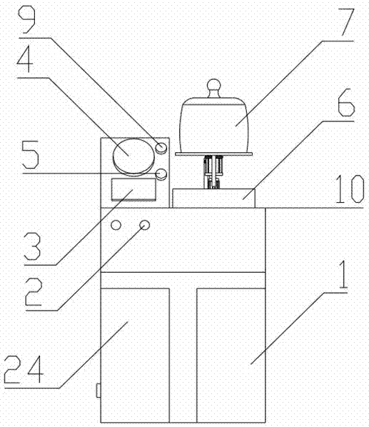
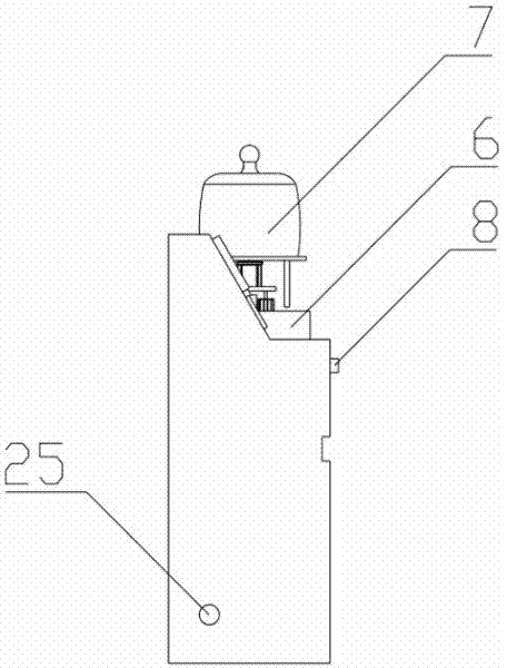
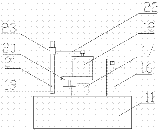
[0018] Such as figure 1 , figure 2 As shown, a workbench 10 is installed on the test bench 1 of the present invention, a bellows automatic welding tool 6 is installed on the table on one side of the workbench 10, and a cylinder inlet pressure gauge 4 and Touch screen 3, work indicator light 9 and alarm indicator light 5, be provided with start switch 8 and emergency stop switch 2 on the front panel of workbench 10, be provided with testbench front door 24 below testbench 1, and external supply gas intake connector 25 is installed on The bottom of the test bench 1 is connected to the internal gas circuit, and a circular tooling fixing base 11 is installed on the top of the workbench 10. Twelve non-penetrating equal-diameter round holes 12 are equally arranged on the bottom of the circular tooling fixing base 11 on the same circle. , corrugated tubes are respectively p...


PUM


Abstract

The invention discloses equipment for automatically welding a vacuum corrugated pipe. According to a fixture for automatically welding the corrugated pipe, a round fixture fixing base is adopted; 12 equant round holes are formed in the round fixture fixing base; a fixed baffle plate is arranged between any two adjacent round holes; proximity switches are respectively arranged on two sides of eachfixed baffle plate along a circumferential direction; an air exhaust hole is formed in the round fixture fixing base, and a hollow shaft is arranged in the center of the round fixture fixing base; anair cylinder is fixed on the base on the side face of the hollow shaft; a baffle plate is arranged on a main shaft of the air cylinder; a stepping motor is fixed on the baffle plate; one end of a link rod is connected with a main shaft of the motor, and the other end of the link rod is connected with a welding pen sleeve; a welding pen is vertically arranged in the welding pen sleeve; one end of a power line and one end of an air source line are introduced from the hollow shaft, and are connected with the stepping motor and the air cylinder respectively; and the other end of the power line and the other end of the air source line are connected with an air pump and a programmable logic controller (PLC) respectively. According to the equipment, the shortcomings of low welding precision, complicated operation, high time consumption, low efficiency and high equipment abrasion during manual welding of the corrugated pipe and the shortcoming that the welding quality and the welding speed are limited by the technical level of operators are overcome.

Description

technical field [0001] The invention relates to an automatic welding device, in particular to a vacuum bellows automatic welding device. Background technique [0002] With the rapid development of our country's national economy, the transportation pipelines of various liquids and gases have increased greatly. Metal bellows are widely used to replace U-shaped tubes because of their many advantages. The current bellows welding methods are all manual welding: fill the bellows rotating tooling with bellows to be welded, cover with a glass sealing cover, vacuumize with a vacuum pump, start to manually rotate the bellows welding tooling, and weld several bellows in turn When finished, take off the glass sealing cover; during the welding process, the size of the weld cannot be accurately observed, and the feeding amount of the electrode cannot be accurately adjusted according to the size of the weld. It can only be fed by experience, and the quality of the weld cannot be controlle...

Claims


Application Information

Patent Timeline
Patent Type & Authority Applications(China)
IPC IPC(8): B23K3/00B23K3/08
Inventor 姚燕薛侠峰赵丹蔡晋辉曾九孙蒋庆
Owner CHINA JILIANG UNIV
Why Eureka
Try Eureka