Welding clamp

A technology of welding fixtures and splints, which is applied in welding equipment, auxiliary welding equipment, welding/cutting auxiliary equipment, etc., and can solve problems such as inability to adapt to welding

Inactive Publication Date: 2012-06-20
WUJIANG SHUANGJING BEARING
View PDF6 Cites 0 Cited by
  • Summary
  • Abstract
  • Description
  • Claims
  • Application Information

AI Technical Summary

Problems solved by technology

Welding the sheet metal into a cylinder first, and then forming it through welding, cutting, rolling and other processes is a way to make infinitely variable speed parts. When welding such thin rings, due to the high welding accuracy requirements, the general fixture to be unable to adapt to the soldering of the product

Method used


Image

  • Welding clamp
  • Welding clamp
  • Welding clamp

Examples


Embodiment Construction

[0015] Below in conjunction with accompanying drawing, the present invention is described in further detail:

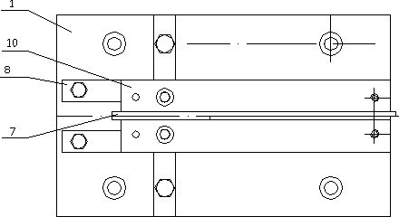
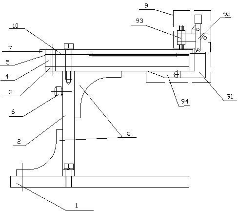
[0016] As shown in the figure: a welding fixture, including a base 1, a support plate 2, a supporting plate 3, a lower splint 4, a gasket 5, an inert gas interface 6, a limit strip 7, a rib 8, and a fixed clamping device 9 , upper splint 10.

[0017] The upper end of the base 1 is vertically arranged with a support plate 2, and the upper end of the support plate 2 is arranged with a supporting plate 3, and the lower splint 4 is fixed on the upper end of the supporting plate 3; a fixed clamping device 9 is arranged at one end of the supporting plate 3 and the lower splint 4.

[0018] The fixed clamping device 9 includes a movable part 91, a fixed frame 92, a fixed buckle 93, and a fixed part 94; the fixed part 94 is fixedly connected to the lower plane of the supporting plate 3, and the movable part 91 becomes an "L" shape, and one end of the movable part 91 It is mov...


PUM


Abstract

The invention relates to a welding clamp. The welding clamp comprises a pedestal, a support column plate, a bearing plate, lower clamping plates, a fixing and clamping device and upper clamping plates, wherein the upper end of the pedestal is vertically provided with the support column plate; the upper end of the support column plate is provided with the bearing plate; the lower clamping plates are fixed on the bearing plate; and the fixing and clamping device is arranged at one end of the bearing plate and the lower clamping plates and is used for pressing the upper clamping plates and the lower clamping plates. The welding clamp provided by the invention makes that the two welded end faces can be kept on one horizontal plane in the clamp, so that the welding is flat, and a weld joint is formed in the middle of the two upper clamping plates; during welding, the welded upper plane is protected by inert gas, and the inert gas of the welded lower plane reaches the space in the middle of the lower clamping plates passing through the support column plate and the bearing plate through a port path, so that the bottom plane of the weld joint is also in atmosphere of the inert gas; and the two planes after welding keep the original gloss.

Description

technical field [0001] The invention relates to a welding fixture. Background technique [0002] The continuously variable transmission part is a circular ring (approximately 195㎜ in diameter, 9.8㎜ in width, and 0.14㎜ in thickness) with a large diameter, a narrow width and a thin thickness. Its material is alloy steel containing more than 10 alloy elements, of which low carbon High nickel, high cobalt and high molybdenum, this kind of material is expensive, and it still needs to be imported and there is no similar cylindrical material. If it is stamped with sheet metal, the material utilization rate is too low. Welding the sheet metal into a cylinder first, and then forming it through welding, cutting, rolling and other processes is a way to make infinitely variable speed parts. When welding such thin rings, due to the high welding accuracy requirements, the general fixture In order to be unable to adapt to the welding of this product. Contents of the invention [0003] ...

Claims


Application Information

Patent Timeline
IPC IPC(8): B23K37/053
Inventor 姜维鸿冯连锁钟伟祥
Owner WUJIANG SHUANGJING BEARING
Why Eureka
Try Eureka