Clamp body for machining side plate of pulley frame, and method for machining and positioning side plate of pulley frame

A clamping body and pulley frame technology, which is applied in the field of mechanical equipment manufacturing, can solve problems such as stress concentration and large deformation, and achieve the effects of high processing precision, simple structure, and easy production

Active Publication Date: 2012-06-20
陕西天达航空标准件有限公司 +1
View PDF9 Cites 5 Cited by
  • Summary
  • Abstract
  • Description
  • Claims
  • Application Information

AI Technical Summary

Problems solved by technology

[0004] The purpose of the present invention is to provide a clamping body for processing the side plate of the pulley frame, which solves the problem that there is no special equipment in the processing of the side plate of the pulley frame in the prior art, and the problems of stress concentration and large deformation after processing on an ordinary platform

Method used


Image

  • Clamp body for machining side plate of pulley frame, and method for machining and positioning side plate of pulley frame
  • Clamp body for machining side plate of pulley frame, and method for machining and positioning side plate of pulley frame
  • Clamp body for machining side plate of pulley frame, and method for machining and positioning side plate of pulley frame

Examples


Embodiment Construction

[0018] The present invention will be described in detail below in conjunction with the accompanying drawings and specific embodiments.

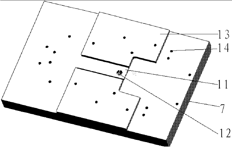
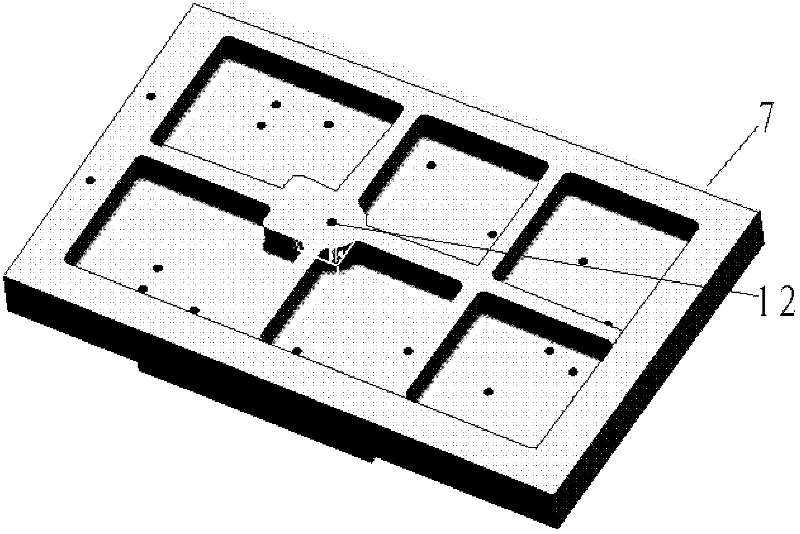
[0019] figure 1 , figure 2 It is a schematic diagram of the structure of the upper and lower surfaces of the clamp body 7 for processing the side plate of the pulley frame of the present invention. The clamp body 7 is made as a casting, and the upper surface is a working surface. Symmetrical steps 13 and many positioning are arranged along both sides of the longitudinal axis of the upper surface. The hole 14 used for installation is provided with a short through groove between the two steps 13. The bottom surface of the short through groove is a positioning surface 11 with high precision. On the positioning surface 11, a step hole 12 is provided. It is a light hole, which is used to install the positioning sleeve, and the lower part of the step hole 12 is a threaded hole, which is used to fix the bolts used for connection; the back structur...


PUM


Abstract

The invention discloses a clamp body for machining a side plate of a pulley frame. The upper surface of the clamp body is a working surface; two sides of a longitudinal axis of the upper surface of the clamp body is provided with symmetrical steps and a plurality of holes for positioning and installation; a short through groove are formed between two steps; the bottom of the short through groove is provided with a section of positioning surface which is provided with a step hole; the upper section of the step hole is provided with a light hole; and the lower end of the step hole is provided with a thread hole. The invention also discloses a method for machining and positioning the side plate of the pulley frame by using the clamp body; during rough machining, four round tables on the lower side of the side plate are used as positioning supporting surfaces, and multi-point positioning and pressing plate pressing modes are adopted; during finish machining, a single-point positioning mode is adopted to prevent deformation, so deformation and error are reduced; left and right pieces are machined at the same tool; and high machining accuracy and matching accuracy are achieved.

Description

technical field [0001] The invention belongs to the technical field of mechanical equipment manufacturing, and relates to a clamping body for processing the side plate of a pulley frame, and also relates to a method for processing and positioning the side plate of a pulley frame by using the clamping body. Background technique [0002] The pulley frame is an important part of the aircraft airdrop device. The side plate of the pulley frame consists of a left side plate and a right side plate. The left and right side plates are symmetrical in structure. When used in pairs, they are large-sized thin-walled special-shaped parts. The thickness is uneven, the shape is complex, and the dimensional accuracy is high. [0003] In the prior art, when conventional multi-point positioning and clamping methods are used for processing, the problem of stress concentration cannot be overcome, which will lead to deformation of the side plate of the pulley frame, and it is difficult to ensure ...

Claims


Application Information

Patent Timeline
Patent Type & Authority Applications(China)
IPC IPC(8): B23Q3/06B23P17/00
Inventor 饶义钟何宁王梁栋熊明柱
Owner 陕西天达航空标准件有限公司
Why Eureka
Try Eureka