Slot structure of guide wheel of linear cutting machine

A cutting machine and wire trough technology, which is applied to work accessories, stone processing equipment, manufacturing tools, etc., can solve the problems of inconsistent thickness chip slicing, wire splicing in cutting operations, and increased wire shaking, etc., to improve yield, Avoid jumpers, cost saving effect

Inactive Publication Date: 2012-06-20
KUNSHAN HANHUI ELECTRONICS TECH CO LTD
View PDF6 Cites 9 Cited by
  • Summary
  • Abstract
  • Description
  • Claims
  • Application Information

AI Technical Summary

Problems solved by technology

Therefore, when applied to cutting operations, the wire at the outlet end 112 will form a smaller wire diameter due to wire loss, and the wire with a smaller wire diameter is likely to cause many problems due to the poor wire groove at the outlet end 112 , for example, the degree of shaking of the wire is intensified, which makes the cut chip wavy, and even chip slices with inconsistent thickness caused by the jumping of the wire; Decrease the yield of chip slicing

Method used


Image

  • Slot structure of guide wheel of linear cutting machine
  • Slot structure of guide wheel of linear cutting machine
  • Slot structure of guide wheel of linear cutting machine

Examples


Embodiment

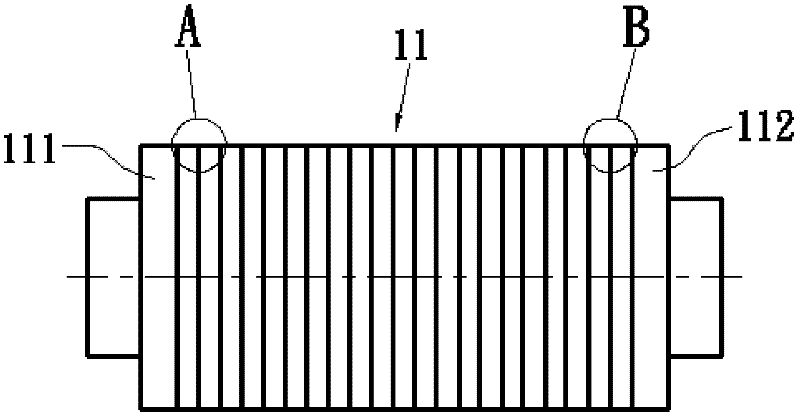
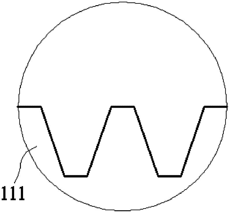
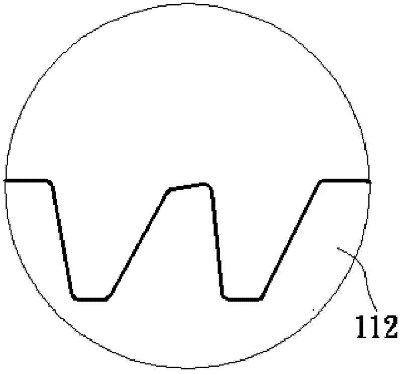
[0021] Embodiment: A wire groove structure of a guide wheel of a wire cutting machine, the guide wheel 11 has an opposite wire-entry end 111 and a wire-out end 112, and the guide wheel is located at the wire-entry end and the wire-outlet end. There are several parallel annular wire grooves 12 in the position between the ends, and the wire 2 of the linear cutting machine is wound between adjacent guide wheels along the annular wire grooves to form several parallel tangent lines. The annular wire slot near the outlet end is the first wire slot 121, the first wire slot is composed of a U-shaped slot 1211 and an arc-shaped slot 1212 integrally connected, and the upper end of the U-shaped slot is integrally formed with the arc-shaped slot The width of the opening 1213 at the upper end of the arc-shaped groove is the same as the diameter of the wire 2 (referring to the initial diameter of the wire).

[0022] The bottom surface of the U-shaped groove is arc-shaped.

[0023] The groo...


PUM


Abstract

The invention discloses a slot structure of a guide wheel of a linear cutting machine. The slot structure is formed by integrally connecting a first slot and an arc-shaped groove through a U-shaped groove, wherein the first slot is close to a wire outlet end; the arc-shaped groove is internally molded at the upper end of the U-shaped groove; the width of an opening at the upper end of the arc-shaped groove is the same as the initial diameter of a wire rod; and the wire rod enters into the U-shaped groove through the opening at the upper end of the arc-shaped groove. Compared with the traditional large-opening U-shaped groove and V-shaped groove, the opening of the first slot provided by the invention is smaller, so as to avoid jumping the wire rod and the like; and the arc-shaped groove can be used for effectively slowing the wire rod to shake and the like; and therefore, according to the slot structure, the wire rod with a small wire diameter, which is formed at the wire outlet end due to wire loss, can be effectively compensated, so that the yield of wafer slices is improved, the service life of the guide wheel is prolonged and the aim of saving the cost is further achieved.

Description

technical field [0001] The invention relates to a guide wheel structure, in particular to a guide wheel structure of a wire cutting machine. Background technique [0002] Solar cells are currently mainly divided into crystalline silicon solar cells and amorphous silicon solar cells. The silicon chips of crystalline silicon solar cells are sliced ​​from silicon wafers. The common way to make silicon wafers by slicing silicon wafers is to use a linear cutting machine to cut free abrasive particles. For example, a linear cutting machine usually includes two rotatable guide wheels and wires assembled on the parallel guide grooves of the guide wheels. , so that a multi-section parallel wire saw is formed; during the cutting operation, the cutting fluid containing cutting powder (such as silicon carbide, etc.) is poured on the parallel wire saw, and at this time, the parallel wire saw is driven by a motor to make the cutting powder and silicon crystal The ingot is contacted with ...

Claims


Application Information

Patent Timeline
Patent Type & Authority Applications(China)
IPC IPC(8): B28D7/00
Inventor 薛东妹
Owner KUNSHAN HANHUI ELECTRONICS TECH CO LTD
Why Eureka
Try Eureka