Linear vibration and overload combinatorial testing method and apparatus thereof

A combined test and line vibration technology, applied in the field of measurement, can solve problems such as product impact differences, no test plan, and non-compliance with combined testing.

Active Publication Date: 2012-06-20
哈尔滨工大瑞驰高新技术有限公司
View PDF3 Cites 20 Cited by
  • Summary
  • Abstract
  • Description
  • Claims
  • Application Information

AI Technical Summary

Problems solved by technology

[0003] For a long time, there has always been a problem for component-level products: what is the difference between the impact of a single environment and a composite environment on the product?
The automatic test system established by Lu Shun in his paper "Development of Accelerometer Comprehensive Test System" (Shanghai Jiaotong University Master's Degree Thesis, 2007) is only suitable for the calibration test of the angular velocity meter, not the comprehensive test; Jia Puzhao in his paper " Steady-state acceleration simulation test equipment: centrifuge design" (see "Spacecraft Environmental Engineering", 2011, Volume 28, No. 2, Page 194-203) The centrifuge designed is only suitable for overload or linear acceleration tests; Li Chunzhi, Li Qisheng, and Niu Baoliang pointed out in their paper "Measurement and Analysis of Centrifuge Structural Vibration under the Combination of Centrifugation and Vibration" (see "Vibration and Shock", 2008, Supplement to Volume 27, Pages 265-267) that currently the vibration table is usually used to The system realizes the vibration-centrifuge composite test by placing the connecting base plate in the centrifuge basket, and no better test plan is given; Cui Shenggang wrote in his thesis "Research on Measurement and Control Problems of Linear Vibration Table" (Harbin Institute of Technology Master's Degree Thesis, 2009 ) analyzed the composition, mathematical model and control method of the wire vibration table, the device is only suitable for the test of wire vibration; Pneumatics, No. 6, 2003, pages 14-17), the hydraulic line vibration table researched in is also only suitable for the line vibration test, none of the above meets the requirements of the combined test

Method used


Image

  • Linear vibration and overload combinatorial testing method and apparatus thereof
  • Linear vibration and overload combinatorial testing method and apparatus thereof
  • Linear vibration and overload combinatorial testing method and apparatus thereof

Examples


Embodiment 1

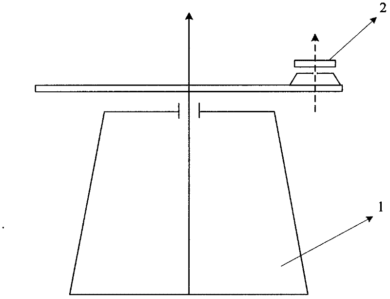
[0017] Example 1: Combination figure 1 , The present invention is a linear vibration and overload combined test device, which is composed of a disc centrifuge and a high-speed rotating platform. The high-speed rotating platform is installed on the disc centrifuge. The rotating shaft of the disc centrifuge and the high-speed rotating platform The rotating shafts are parallel, and the speed of the disc centrifuge and the speed of the high-speed rotating platform can be adjusted.

[0018] A combined testing method of linear vibration and overload of the present invention, the steps are as follows:

[0019] Step 1: Install the measured inertial instrument on the high-speed rotating platform, and transmit the test signal to the ground monitoring computer through the slip ring;

[0020] Step 2: Power up the disc centrifuge and high-speed rotating platform;

[0021] Step 3: Calibrate the input shaft of the measured inertial instrument;

[0022] Step 4: Turn on the control program of the disc ...

Embodiment 2

[0024] Example 2: Combination figure 1 , The method for testing the combined linear vibration and overload of the present invention, the steps are as follows:

[0025] (1) Install the measured inertial instrument on the high-speed rotating platform, align the input shaft reference of the measured inertial instrument with the zero position of the high-speed rotating platform (allowable error is 10 arc seconds), and connect the table with a test signal cable during installation The slip ring on the upper side and the output signal socket of the measured inertial instrument, and then use another signal cable to connect the signal base of the centrifuge base and the ground monitoring computer acquisition card, so that the inertial instrument signal is transmitted to the ground monitoring computer through the slip ring;

[0026] (2) Power up the disc centrifuge and high-speed rotating platform and control them to the zero position;

[0027] (3) After installing the input shaft of the meas...

Embodiment 3

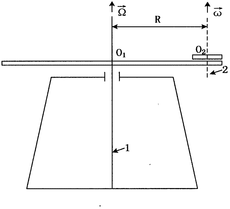
[0030] Example 3: Combination figure 1 , figure 2 , The working principle of the present invention is as follows:

[0031] figure 2 Among them, "1" is the rotary spindle of the disc centrifuge, "2" is the rotary axis of the high-speed rotating platform, the "1" axis and the "2" axis are parallel and the distance between the axes is R, Is the rotational angular velocity vector of the rotating main shaft of the disc centrifuge, Is the rotational angular velocity vector of the rotary axis of the high-speed rotating platform, which specifies with The positive direction is straight up. Because O 2 The point is always the point on the disc of the disc centrifuge, so O 2 If there is no Coriolis acceleration and relative acceleration, O can be obtained 2 The absolute acceleration of the fixed coordinate system relative to the ground base at a point is Its size is RΩ 2 , Its direction is O 2 The point along the centrifugal disc points to the center of rotation of the centrifuge. S...


PUM


Abstract

The invention provides a linear vibration and overload combinatorial testing method and an apparatus thereof. The apparatus is composed of a disc centrifuge and a high-speed rotation platform. The high-speed rotation platform is arranged on the disc centrifuge. The shaft of the disc centrifuge is parallel to the shaft of the high-speed rotation platform. The testing method comprises the steps that: an inertial instrument requiring testing is arranged on the rotation platform; testing signals are transmitted to a ground monitoring computer through a slide ring; the centrifuge and the high-speed rotation platform are powered up, and null positions are controlled; an input shaft of the inertial instrument is calibrated; a controlling program is started; rotation speeds of the centrifuge and the high-speed rotation platform are adjusted; and the performance of the inertial instrument is analyzed. With the apparatus and the method provided by the invention, technology realization difficulties caused by large weight and volume of a electromagnetic vibration shaker can be greatly reduced; and high-precision testing is realized while environmental test is achieved.

Description

(1) Technical field [0001] The invention relates to measurement technology, in particular to a combined testing method and device of linear vibration and overload. (2) Background technology [0002] The inertial navigation test device is the key equipment in the research of inertial instrument and inertial measurement system. The comprehensive environment simulation equipment mainly based on the centrifuge is a kind of simulation equipment integrating environment and mechanical environment that developed earlier and faster. In the 19's, a composite environment simulation test equipment with a centrifuge as the main body was manufactured. The general practice of this equipment is to install equipment that can simulate temperature, altitude, humidity, vibration or other environmental conditions at one end of the centrifuge arm. The main purpose of the equipment is to simulate the effects of the composite environment experienced by aircraft, missile warheads, satellites and spacecr...

Claims


Application Information

Patent Timeline
IPC IPC(8): G01C25/00
Inventor 王常虹曾庆双马广程伊国兴夏红伟
Owner 哈尔滨工大瑞驰高新技术有限公司
Why Eureka
Try Eureka