
Movable micro turbine jet engine test bed

A jet engine and micro-turbine technology, applied in the direction of internal combustion engine testing, etc., can solve problems such as poor flexibility and immovability of small test benches

Active Publication Date: 2012-06-20
BEIHANG UNIV
View PDF8 Cites 33 Cited by
  • Summary
  • Abstract
  • Description
  • Claims
  • Application Information

AI Technical Summary

Problems solved by technology

[0004] The purpose of this invention is to provide a kind of movable micro-turbojet engine test stand, which can solve the problem that the existing small-scale test stand is immovable and poor in flexibility, and at the same time, the air intake rate, rotating speed, compressor after the micro-turbojet engine Accurate measurement of temperature, pressure, thrust, and fuel consumption rate, providing equipment support for performance measurement of micro turbojet engines

Method used


Image

  • Movable micro turbine jet engine test bed
  • Movable micro turbine jet engine test bed
  • Movable micro turbine jet engine test bed

Examples


Embodiment Construction

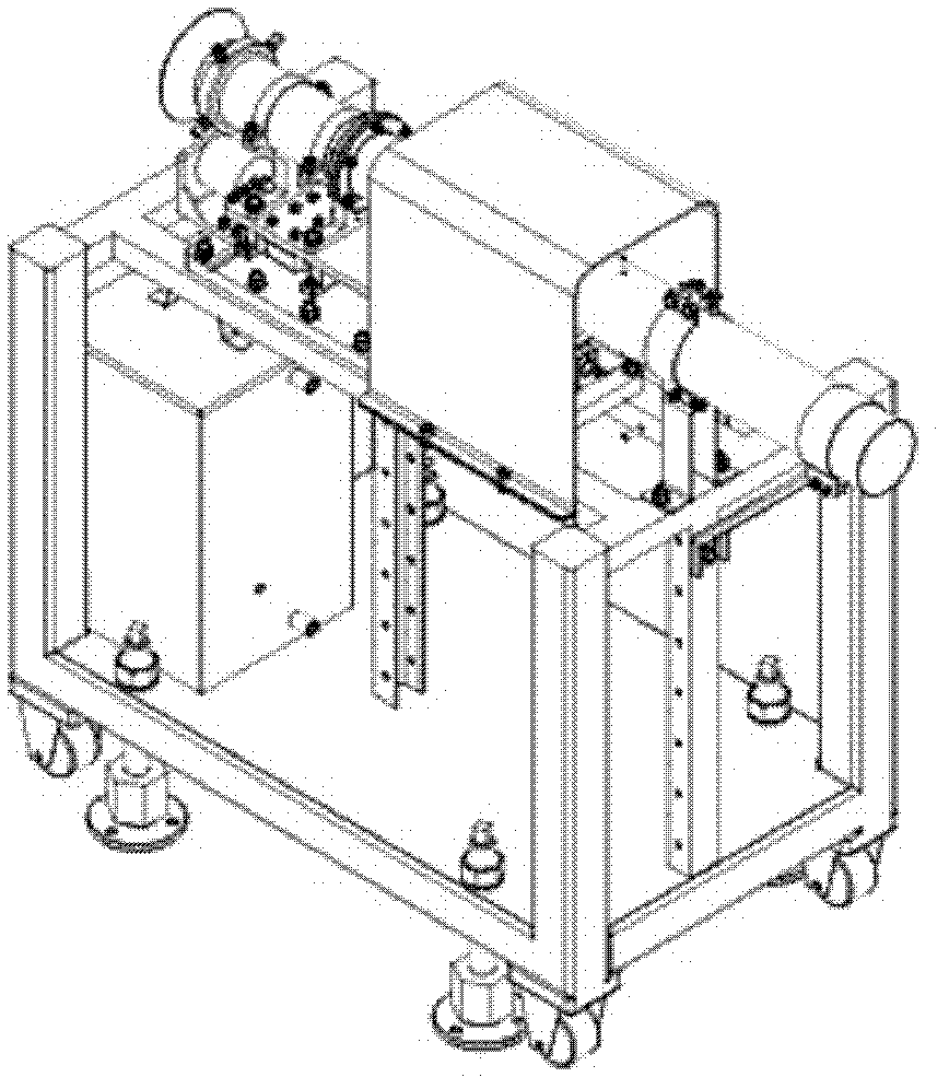
[0026] A movable miniature turbojet engine test stand of the present invention is composed of two parts, a test stand and a control cabinet. connected; the control cabinet is equipped with various instruments and computers to receive experimental data and control the running state of the micro turbojet engine.

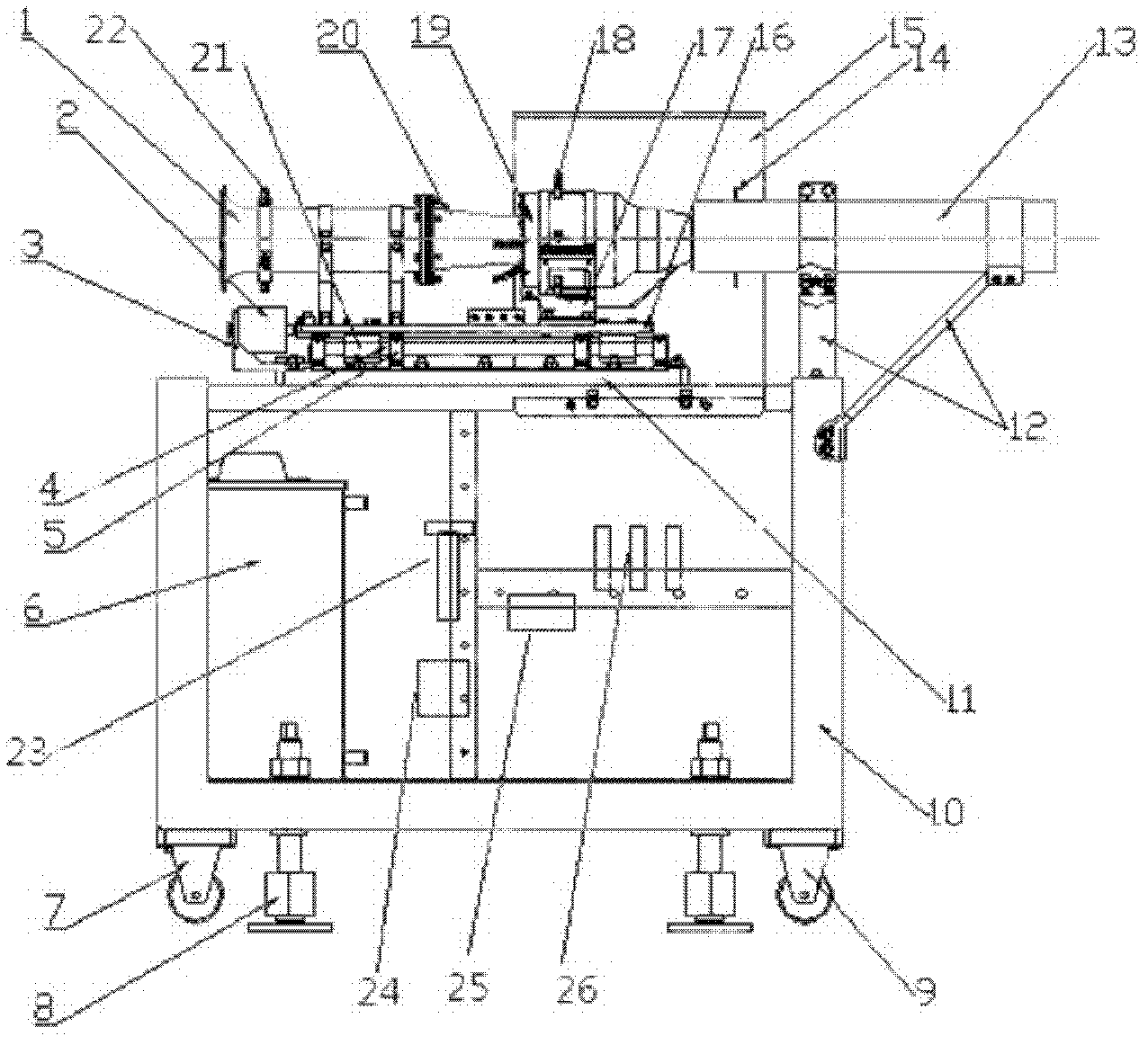
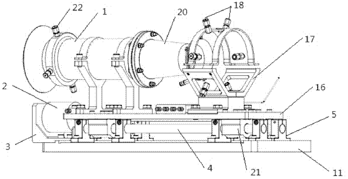
[0027] See figure 1 , the test bench is an open structure, which is convenient for understanding and observing the connection method and theme structure of various sensors. It consists of a flow measuring tube 1, a load cell 2, a load cell bracket 3, a slide rail shaft 4, a slide rail shaft support 5, an oil tank 6, a moving wheel 7, a screw support 8, a fixed wheel 9, and a main support steel frame 10 , fixed plate 11, tail nozzle bracket 12, tail nozzle 13, temperature sensor 14, protective cover 15, slide plate 16, engine support seat 17, temperature sensor and pressure measuring joint 18, micro turbojet engine 19, front inner guide Flow cover 20, sliding plate co...


PUM


Abstract

The invention relates to a movable micro turbine jet engine test bed, which consists of a test bed rack and a control cabinet. An engine to be tested and various measurement sensors are installed on the test bed rack. The test bed rack is connected with the control cabinet through conducting wires. Various meters and a computer are installed in the control cabinet. The control cabinet is used for receiving test data and controlling the running state of the engine. The test bed rack consists of a flow measuring pipe, a weighing sensor, a weighing sensor support, sliding rail shafts, sliding rail shaft supports, an oil tank, moving wheels, fixed wheels, lead screw supports, a main body support steel frame, a fixing plate, a tail jet pipe support, a tail jet pipe, temperature sensors, a protection cover, a sliding plate, an engine supporting base, a pressure measuring joint, the engine to be tested, a front inner flow guide cover, sliding plate connecting blocks, a flow meter, a micro differential pressure transmitter, an electronic control unit (ECU) and pressure transmitters. The control cabinet consists of a cabinet body, various meters, the computer, four corner wheels and an ECU control assembly. The movable micro turbine jet engine test bed is flexible and convenient, and provides an equipment support for the accurate determination of the performance of the micro turbine jet engine.

Description

technical field [0001] The invention relates to a movable micro-turbojet engine test stand, which can measure parameters such as the micro-turbojet engine speed, intake air flow, fuel consumption rate, temperature and pressure after a compressor. The invention belongs to the technical field of aero-engine testing. Background technique [0002] The aeroengine is an important part of the aircraft and is the power source of the aircraft. The rise of small aircraft research has brought forth the need for sophisticated testing of the characteristics of small aeroengines. But a small engine is not a reduction of a large engine, so it has its own unique properties, such as the rotor speed of a small and medium engine is usually much higher than that of a large engine. However, the measurement sensitivity of a large aero-engine test bench cannot meet the test requirements of a small-scale engine. At present, most small aero-engine test benches are simple fixed frames, which can o...

Claims


Application Information

Patent Timeline
IPC IPC(8): G01M15/05
Inventor 胡殿印曹福粱王荣桥樊江
Owner BEIHANG UNIV
Learn More