Online abrasion detection method and system for pantograph of electric locomotive

A technology for electric locomotives and detection methods, applied in the direction of optical testing flaws/defects, etc., can solve the problems of low reliability, inability to fully reflect the wear of the pantograph, complex system structure, etc., and achieve the effect of improving accuracy and real-time performance

Inactive Publication Date: 2013-05-15
NANJING UNIV
View PDF3 Cites 0 Cited by
  • Summary
  • Abstract
  • Description
  • Claims
  • Application Information

AI Technical Summary

Problems solved by technology

Among these methods, some systems have complex structures and low reliability; some systems can only obtain the condition of the front side of the pantograph, and cannot fully reflect the wear and tear of the pantograph

Method used


Image

  • Online abrasion detection method and system for pantograph of electric locomotive
  • Online abrasion detection method and system for pantograph of electric locomotive
  • Online abrasion detection method and system for pantograph of electric locomotive

Examples


Embodiment Construction

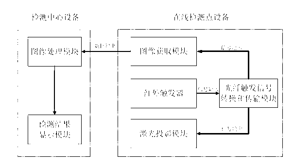
[0024] like figure 1 As shown, an electric locomotive pantograph on-line wear detection system includes on-line monitoring point equipment and testing center equipment.

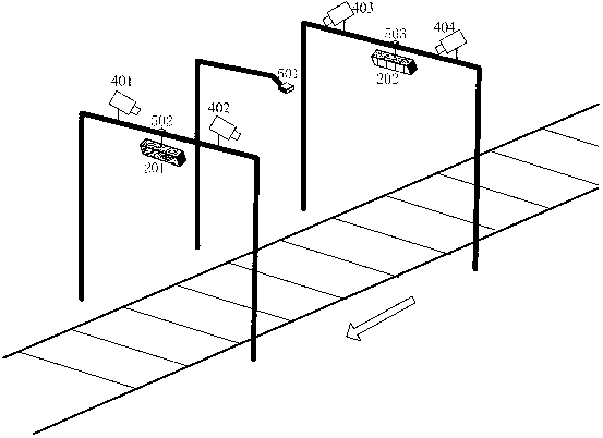
[0025] figure 2 It is a schematic diagram of the online detection point equipment. Column 1, column 2 and column 3 have the same height, infrared trigger 101 is installed on column 2, digital cameras 401, 402 and line laser array 201 are installed on column 1, digital cameras 403, 404 and line laser array 202 are installed on on column 3.

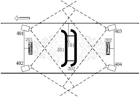
[0026] image 3 It is a top view of the online detection point equipment. A pantograph includes two pantograph graphite strips 301 and 302 . The digital cameras 401 and 402 take pictures in a backward and downward manner, and the overlapping field of view of the two includes the pantograph graphite strip 301 . The digital cameras 403 and 404 take pictures in a forward and downward manner, and the overlapping range of their fields of view includes the pantograph gra...


PUM


Abstract

The invention relates to an online abrasion detection method and system for a pantograph of an electric locomotive. The online abrasion real-time detection system of the pantograph comprises a laser projection module, an image acquisition module and a fiber trigger signal conversion and transmission module and is further provided with a first upright post, a second upright post and a third upright post, wherein the laser projection module consists of two linear laser arrays; each linear laser array comprises a plurality of linear lasers; laser rays emitted by the linear lasers are projected onto the pantograph in a parallel manner; the distance between the faculas of every two adjacent linear lasers is kept at the magnitude of millimeter; the first upright post, the second upright post and the third upright post are equidistantly arranged; the first linear laser array, a first digital camera and a second digital camera are mounted on the first upright post; an infrared trigger is mounted on the second upright post; the second linear laser array, a third digital camera and a fourth digital camera are mounted on the third upright post; and the infrared trigger is mounted at a position on the second upright post such that the digital cameras can photograph the pantograph by forwardly aligning to the center of a track in the depression angles of 20-30 DEG.

Description

technical field [0001] The invention relates to a monitoring method and system for measuring the pantograph wear of an electric locomotive, in particular to a pantograph online wear detection method and system based on structured light binocular stereo vision. Background technique [0002] The electric locomotive pantograph is a device for electrified railway electric locomotives to receive current from the catenary. Its slide strips are in direct contact with the catenary wires and receive current from the catenary wires for use by the locomotive. The quality of the pantograph directly affects the safe operation of the train. The excessive wear of the pantograph slide not only affects the normal power supply of the electric locomotive, but the resulting arc discharge will further aggravate the wear of the pantograph slide and catenary. With the rapid development of high-speed railways, higher requirements are put forward for the reliable operation of pantographs, and it is ...

Claims


Application Information

Patent Timeline
Patent Type & Authority Patents(China)
IPC IPC(8): G01N21/89
Inventor 王顺张旭苹戚力张益昕杨国文
Owner NANJING UNIV
Why Eureka
Try Eureka