Surface velocity and flow direction measuring device

A technology for measuring device and surface flow velocity, which is applied in measuring device, fluid velocity measurement, velocity/acceleration/impact measurement, etc. It can solve problems such as difficulty in instrument tracking and positioning, harsh measurement conditions, and large errors in measuring flow velocity and flow direction. It is convenient for deploying and recovering operations, saving manpower and material resources, and changing the effect of working mode

Inactive Publication Date: 2012-06-20
CCCC THIRD HARBOR CONSULTANTS
View PDF2 Cites 11 Cited by
  • Summary
  • Abstract
  • Description
  • Claims
  • Application Information

AI Technical Summary

Problems solved by technology

[0003] 1. The accuracy is not high, and the measurement conditions are relatively harsh. Generally, three or more stations need to be deployed on the shore for simultaneous observation. Each station is equipped with one person for observation and recording, and one transportation ship is used for buoy release and recovery. A lot of manpower and material resources, and the labor intensity is high, and it is easily affected by human factors and the environment
[0004] 2. The buoy drifts with the waves in the water. Due to the small size of the buoy, it is difficult to track and locate the instrument. It is difficult to ensure that the readings are recorded synchronously between the stations. This requires skilled basic skills and rich experience in rendezvous
[0005] 3. The polar coordinate method of the total station also has the above disadvantages, and it is difficult to realize the mirror positioning when the flow velocity is large
As a result, the measurement of flow velocity and flow direction in the project has large errors, and the investment cost is too high

Method used


Image

  • Surface velocity and flow direction measuring device
  • Surface velocity and flow direction measuring device
  • Surface velocity and flow direction measuring device

Examples


Embodiment Construction

[0027] In order to make the technical means, creative features, goals and effects achieved by the present invention easy to understand, the present invention will be further described below in conjunction with specific illustrations.

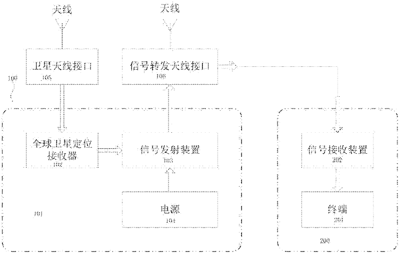
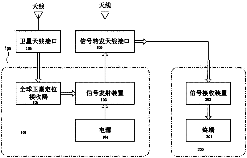
[0028] see figure 1 , the surface velocity and flow direction measurement device provided by the present invention, the measurement device uses the global satellite positioning system for real-time positioning, thereby completing the measurement of river or ocean surface velocity and flow direction.

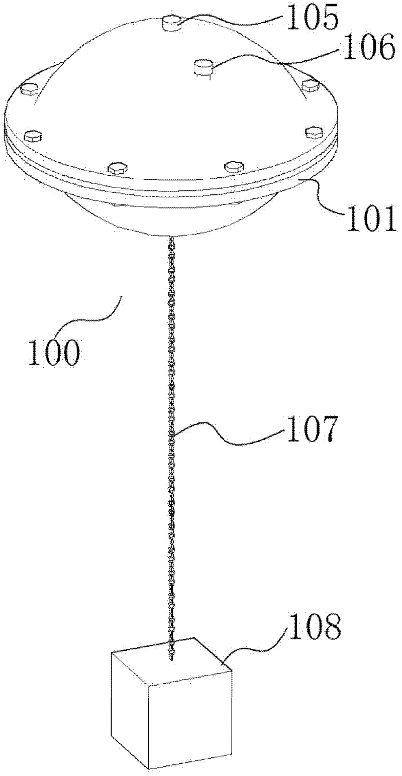
[0029] In terms of structural composition, the measurement device includes two parts: a buoy body 100 and a remote terminal 200 .

[0030] The buoy body 100 is the measurement core of the whole device, which obtains its own position coordinate information in real time through the global satellite positioning system, and records and transmits the position coordinate information to the remote terminal.

[0031] The buoy body 100 includes three parts...


PUM


Abstract

The invention discloses a device for measuring a surface velocity and a flow direction of a river, a rivus and the sea. A buoy shell, a mooring cable and a counter weight are arranged on the water. A global positioning system receiver, a signal transmitting device and a power supply are arranged in the buoy shell. A signal receiving device and a terminal are arranged on the bank. In the process of measuring the surface velocity and the flow direction, the global positioning system receiver in the buoy shell receives a signal transmitted by a satellite, so that position coordinates of a location point are known; the point is preserved in a positioning receiver memory and the signal is simultaneously transmitted through the signal transmitting device; and the receiving device receives the signal and is connected with the terminal, so that the real-time monitoring and data processing are realized. The flow velocity and the flow direction are continuously measured, the process of signal receiving, storage, transmitting, far-end receiving and monitoring and processing is circularly carried out, and the work of measuring the flow velocity and the flow direction is automatically completed. According to the device, the middle-distance and remote wireless transmission can be realized in a large space range, the flow velocity and the flow direction are monitored in real time, and manpower and material resources are effectively saved.

Description

technical field [0001] The invention relates to a communication technology for realizing mid-range and long-distance wireless transmission, in particular to a measuring device for measuring surface flow velocity and flow direction data of rivers, rivers and seas. Background technique [0002] The traditional surface velocity and flow direction measurement methods generally use theodolite to locate with the forward intersection method or the polar coordinate method of the total station (according to the Ministry of Communications "Water Transport Engineering Measurement Specifications" JTJ 203-2001, 7.3 and 9.3 regulations). This method has the following disadvantages: [0003] 1. The accuracy is not high, and the measurement conditions are relatively harsh. Generally, three or more stations need to be deployed on the shore for simultaneous observation. Each station is equipped with one person for observation and recording, and one transportation ship is used for buoy release...

Claims


Application Information

Patent Timeline
Patent Type & Authority Applications(China)
IPC IPC(8): G01P5/00G01P13/02G01S19/52
Inventor 钮建定胡建平赵磊虞祖培王付坤
Owner CCCC THIRD HARBOR CONSULTANTS
Why Eureka
Try Eureka