Electronic ballast and energy saving lamp adopting same

An electronic ballast and capacitor technology, applied in the field of starting lighting equipment, can solve the problems of low power factor, poor anti-interference ability, low reliability, etc. dangerous effect

Inactive Publication Date: 2012-06-20
贺宝光
View PDF5 Cites 0 Cited by
  • Summary
  • Abstract
  • Description
  • Claims
  • Application Information

AI Technical Summary

Problems solved by technology

[0002] The existing electronic ballasts have low power factor, high power consumption, poor anti-interference ability and low reliability, so they are not suitable for lighting lamps in special flammable and explosive environments such as mines and petrochemical in

Method used


Image

  • Electronic ballast and energy saving lamp adopting same
  • Electronic ballast and energy saving lamp adopting same

Examples


Embodiment Construction

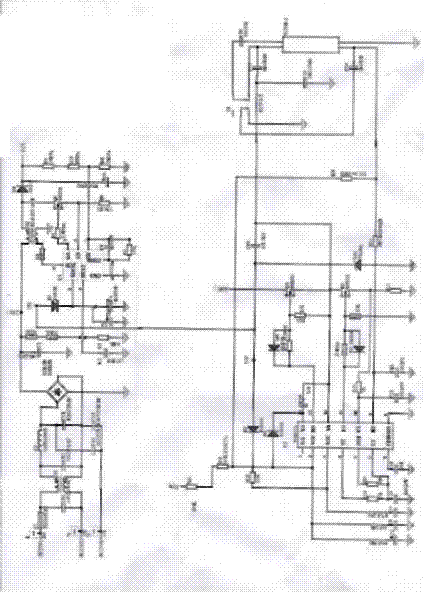
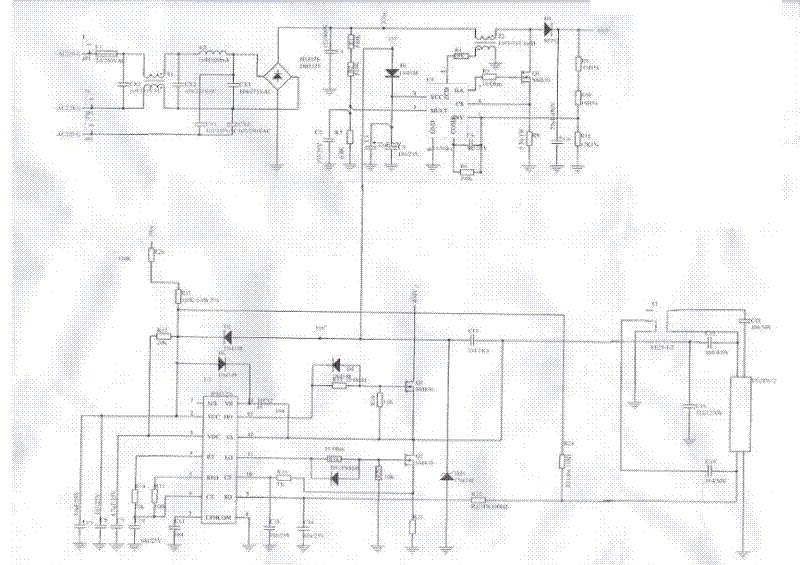
[0022] As shown in the attached figure, an electronic ballast has a source filter circuit, a rectifier filter circuit connected to the active filter circuit, a high-frequency resonance circuit connected to the rectification filter circuit, and a negative feedback circuit connected to the high-frequency resonance circuit The circuit is a load circuit connected with the negative feedback circuit; a power factor correction circuit is connected between the rectification filter circuit and the high frequency resonant circuit.

[0023] The active filter circuit is a π-type active filter circuit composed of transformer T1, inductor L2, and capacitors CX1, CX2, CX3, CY1, and CY2; one end of the inductor L2 is connected to the primary winding of the transformer T1, and the other end is grounded through the capacitor CY1, and the capacitor CY2 and CX3 are connected in series at both ends of capacitor CY1 in parallel, capacitor CX1 is connected in parallel at both ends of the power supply...


PUM


Abstract

The invention discloses an electronic ballast and an energy saving lamp adopting the same and belongs to a lighting startup device. The ballast is provided with an active filter circuit, a rectification filter circuit connected with the active filter circuit, a high-frequency resonance circuit connected with the rectification filter circuit, and a load circuit connected with the high-frequency resonance circuit; a power factor correction circuit is connected between the rectification filter circuit and the high-frequency resonance circuit; and a negative feedback circuit is connected between the high-frequency resonance circuit and the load circuit. The electronic ballast is adopted by an illuminating lamp. The electronic ballast has the advantages of interference resistance, high power factor, high safety and reliability and long service life.

Description

technical field [0001] The invention relates to a start-up lighting device, in particular to an electronic ballast and an energy-saving lamp using the electronic ballast, which can be used for general lighting, and is especially suitable for lighting in inflammable and explosive environments such as mines and petrochemical industries. Background technique [0002] The existing electronic ballasts have low power factor, high power consumption, poor anti-interference ability and low reliability, and are not suitable for lighting lamps in special flammable and explosive environments such as mines and petrochemical industries. Due to the need, the lighting lamps under the mine are always in the lighting state. Due to the low power factor of the ballast and high power consumption, the service life of the lighting lamps is reduced, and the lamp tubes need to be replaced frequently. Contents of the invention [0003] In order to overcome the above-mentioned shortcomings of the pr...

Claims


Application Information

Patent Timeline
IPC IPC(8): H05B41/285H01J61/30H02M1/12H02M1/42
CPCY02B70/126Y02B70/10
Inventor 贺宝光
Owner 贺宝光
Why Eureka
Try Eureka