Optical communication module

An optical communication module and optical signal technology, which is applied in the direction of optics, light guides, lasers, etc., can solve the problems of reduced connection terminal strength, difficulty in thinning, and reduced optical communication accuracy, achieving improved strength, high reliability, and high communication accuracy Effect

Active Publication Date: 2012-06-20
AUTONETWORKS TECH LTD +2
View PDF9 Cites 3 Cited by
  • Summary
  • Abstract
  • Description
  • Claims
  • Application Information

AI Technical Summary

Problems solved by technology

In order to form the opening 31 with a short width with high precision, it is necessary to reduce the thickness of the conductive plate 30. However, since one end of the conductive plate 30 is exposed outside the OSA1 and constitutes a connection terminal with an external device, there is a problem due to the thinning of the conductive plate 30. , the strength of the connection terminal may decrease, and the problem of difficulty in thinning
[0014] In addition, since the upper side of the base 10 of OSA1 on which the laser diode 20 is mounted and the lower side opposite to it are molded by different molds, the diameter ratio of the first lens 14 integrally formed on the upper side of the base 10 cannot be made conductive. The width of the opening 31 of the plate 30 is large
Therefore, when the width of the opening 31 of the conductive plate 30 becomes narrow along with the miniaturization of the laser diode 20, the first lens 14 must be miniaturized, and the accuracy of optical communication may decrease.

Method used


Image

  • Optical communication module
  • Optical communication module
  • Optical communication module

Examples


Deformed example 1

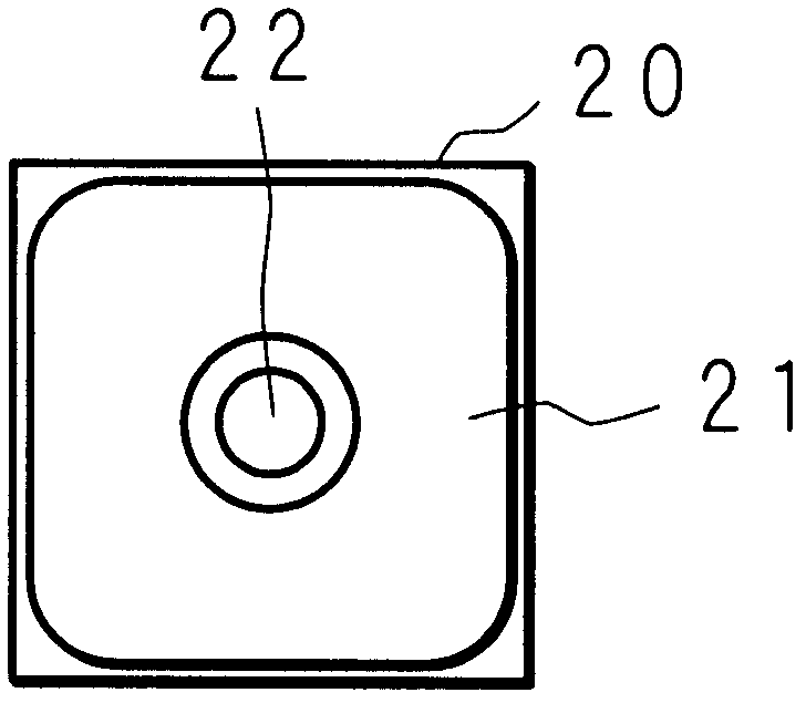
[0125] Figure 9A and Figure 9B It is a schematic diagram showing the structure of the light transmission table 70a included in the optical communication module according to Modification 1 of the present invention, Figure 9A Indicates the structure above the light-passing table 70a, Figure 9B It shows the structure of the lower surface of the light transmission table 70a. the above Figure 3A and Figure 3B The illustrated light-transmitting table 70 is formed of a translucent synthetic resin, and the main body of the light-transmitting table 70 forms a light-transmitting portion through which light passes, but it is not limited thereto. The light transmission stand 70 a of Modification 1 is formed of a synthetic resin that does not transmit light, and has a substantially circular light transmission hole 71 that allows light to pass through the substantially center in a planar view. Thus, the laser diode 20 connected to the conductive plate 60 provided on the upper sur...

Deformed example 2

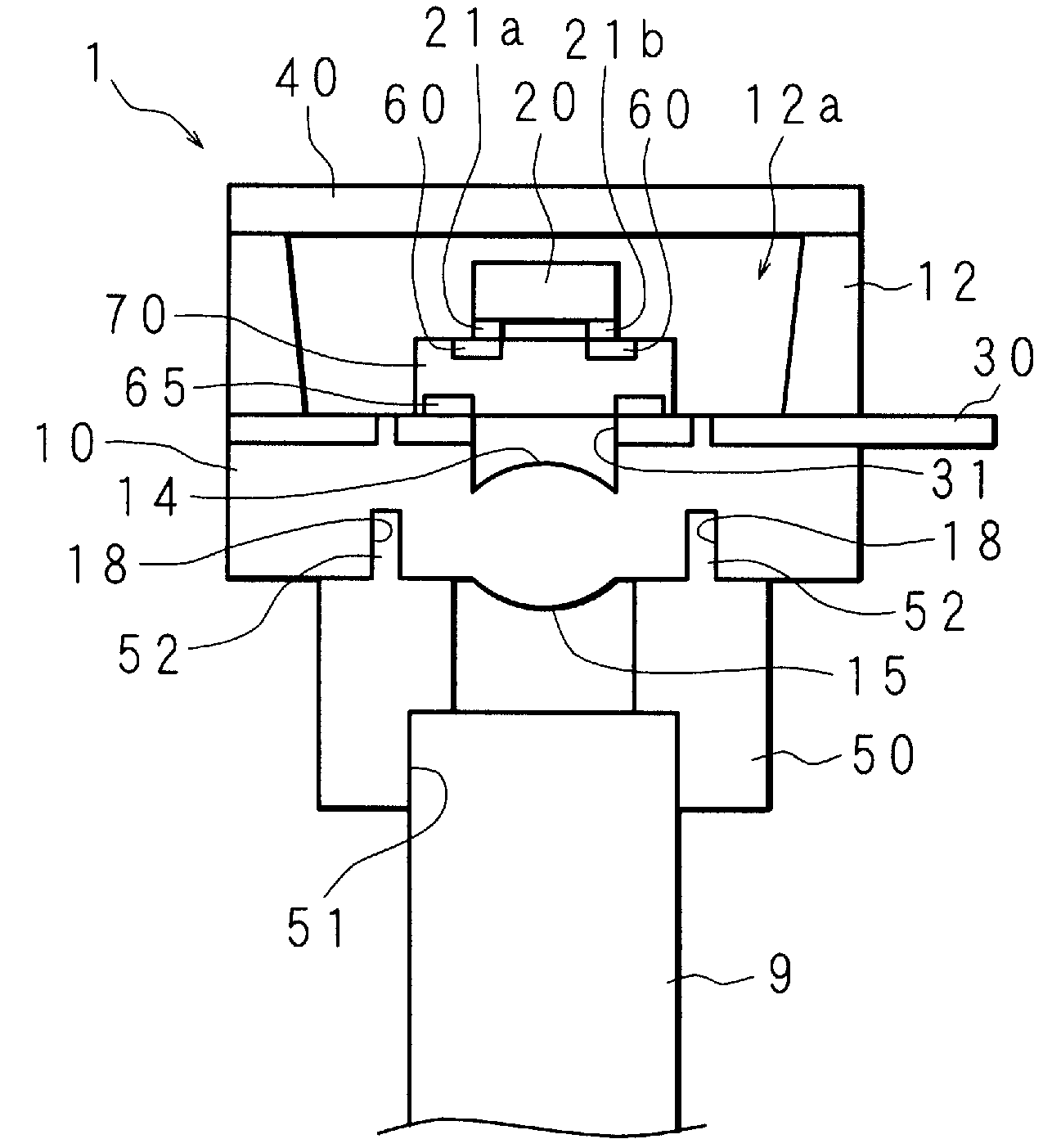
[0128] Figure 10 A schematic cross-sectional view showing the structure of an optical communication module according to Modification 2 of the present invention. The light transmitting table 70b of the OSA1 according to Modification 2 has a substantially square plate shape larger than the laser diode 20 in plan view, and is made of metal. Therefore, the light-transmitting table 70b has no light-transmitting property, and a substantially circular light-transmitting hole 71 is formed at the substantially center in a planar view.

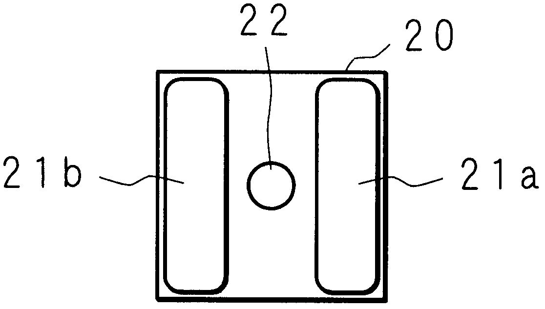
[0129] That is, the light-passing table 70b of Modification 2 is to Figure 9A and Figure 9B The form in which the light transmission table 70a and the conductive plates 60 and 65 of the above-mentioned Modification 1 are integrated is shown. In other words, the light-transmitting table 70b of Modification 2 has the functions of the conductive plates 60 and 65 on the light-transmitting table 70a by making the light-transmitting table 70a of Modific...


PUM


Abstract

Disclosed is an optical communication module in which the thickness of an electrically conductive plate such as a lead frame needs not to be reduced and the size of a lens needs not to be reduced when the size of a photoelectronic element such as a laser diode or a photo diode is reduced. A laser diode (20) is connected and fixed to an electrically conductive plate (60) that is arranged on the upper surface of a light-permeable light-passing table (70), and the light-passing table (70) is connected and fixed to an electrically conductive plate (30) that is arranged on the upper surface of a light-permeable base (10). A first lens (14) and a second lens (15) are respectively formed on the upper surface and the lower surface of the base (10) in an integral manner. The laser diode (20) enables the sending of an optical signal through a gap of the electrically conductive plate (60), the light-permeable light-passing table (70), an opening of an electrically conductive plate (65), an opening (31) of the electrically conductive plate (30), the first lens (14), the light-permeable base (10) and the second lens (15).

Description

technical field [0001] The present invention relates to an optical communication module that encapsulates components such as laser diodes and / or photodiodes for optical communication. Background technique [0002] Currently, optical communication using optical fibers or the like is widely spread. Optical communication is carried out by converting electrical signals into optical signals through light-emitting elements such as laser diodes, receiving and receiving optical signals through optical fibers, and converting received optical signals into electrical signals by light-receiving elements such as photodiodes (hereinafter, these light-emitting elements and light-receiving elements are called for optoelectronic components). Therefore, an optical communication module in which a photoelectric element such as a laser diode and / or a photodiode and peripheral circuit elements for operating the photoelectric element are used as one package is widely used. The optical communicat...

Claims


Application Information

Patent Timeline
Patent Type & Authority Applications(China)
IPC IPC(8): H01S5/022H01L31/0232
CPCG02B6/42G02B6/423H01L31/02325G02B6/4206H01S5/02284H01S5/02288H04B10/50H01L2224/48091H01S5/02251H01S5/02253H01L2924/00014
Inventor 林茂郎高木敏男
Owner AUTONETWORKS TECH LTD
Why Eureka
Try Eureka