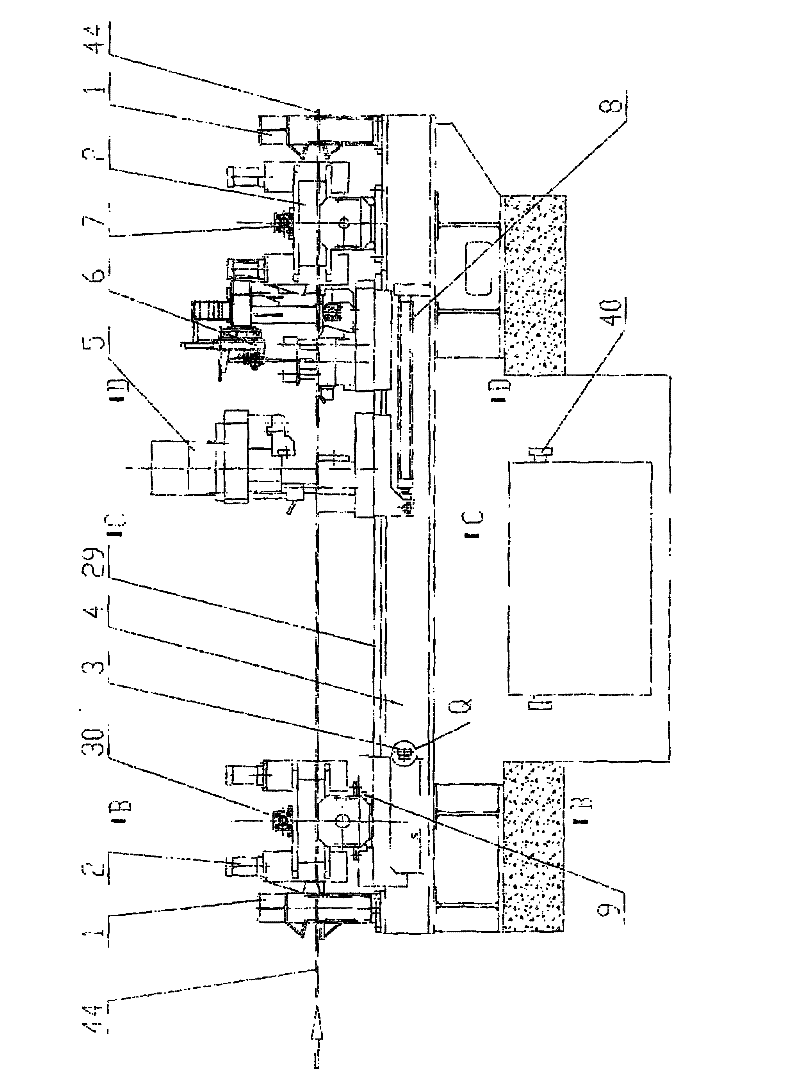
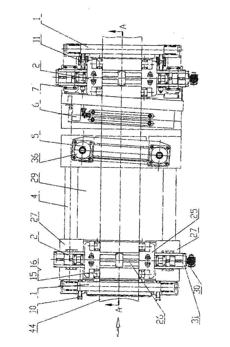
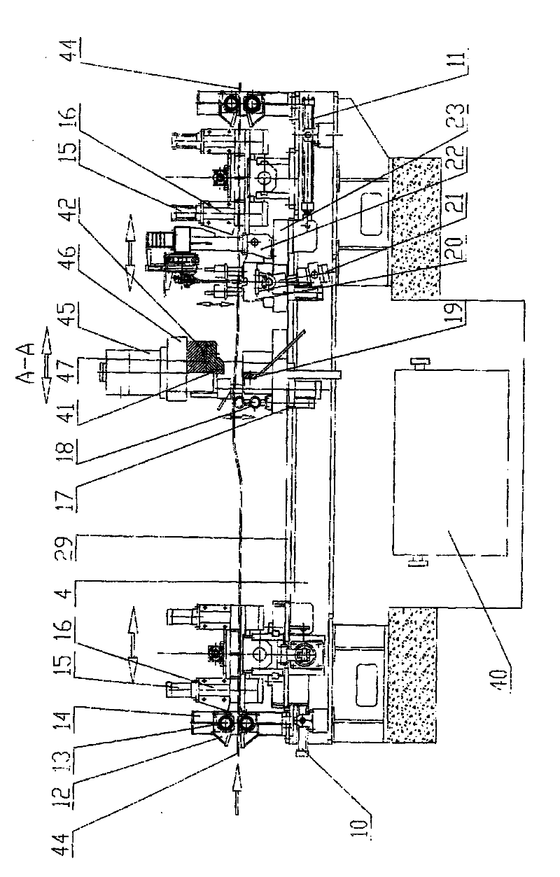
[0009] The object of the present invention is achieved by adopting the following technical scheme: the shear
butt welding machine is characterized in that its structure is mainly composed of flat rollers, pinch centering devices,
stroke stops, bases, shearing devices, welding device, fixing bolts and
waste collection frame, the base is composed of front and rear beams, on one end of the front and rear beams of the base, a flat roller driven by a strip pinch machine is installed to pinch the
strip steel, and the top surface of the base following the flat roller The front and rear sliding seats are installed symmetrically on the front and rear beams of the front and rear sliding seats, and the pinch centering device, shearing device, welding device sliding along the sliding seat are installed in the front and rear sliding seats in sequence, and the welding device following the sliding The front and rear beam ends of the rear base are fixed to the fixed pinch centering device and flat rollers on the base by fixing bolts; a stroke stopper is installed on the side of the base behind the sliding pinch centering device, and the sliding The foundation between the pinch centering device and the sliding shearing device is provided with a
waste collection frame; each of the pinch centering devices is composed of a centering
hydraulic cylinder, a frame, a lead screw motor
reducer, a lead screw , lead screw seat, screw nut, centering roller seat
assembly, guide block and guide block driving device, the machine base driven by the centering
hydraulic cylinder is respectively installed in the front and rear slide seats, and the front and rear slide seats are respectively installed. Two screw seats are installed symmetrically on the two outer ends at the center of the top surface of the rear machine base, and a screw with left and right thread segments driven by a screw motor
reducer is installed in the two screw seats. , The right thread section is screwed to connect the two wire nuts that move synchronously, and two pairs of centering roller seat assemblies that move synchronously are symmetrically installed on the outside of each thread nut; Two guide blocks are symmetrically arranged on the planes of the two machine bases, and a guide block driving device is installed on the bottom surface of the sliding seat. When the two guide blocks slide in the guide groove, the two guide blocks are driven to slide in the guide groove by the guide block driving device, so as to realize two The front and rear movement of the centering roller seat
assembly; the shearing device drives two shearing devices respectively through two shearing moving cylinders symmetrically installed on both sides of the base, and each shearing device is powered by a shearing
hydraulic pressure. Cylinder, shearing beam, dynamic shear seat, adjusting clearance screw and nut, clamping beam, clamping
hydraulic cylinder, support roller, support hydraulic cylinder, shearing base, fixed shear blade and dynamic shear blade, the fixed shear blade The blade is connected to the shearing base, and the moving shearing blade is installed on it. The moving shearing seat is connected to the shearing beam through the sliding chute and the screw. The adjusting clearance screw and nut can push the moving shearing seat along the direction of the sliding chute Move to realize the adjustment of the gap between the movable shear blade and the fixed shear blade; the two shear hydraulic cylinders symmetrically installed on the dynamic shear base synchronously push the dynamic shear base to move down to
cut the strip steel; this improves the prior art single The
cantilever shear blade driven by the cylinder has the
disadvantage of uneven force; two clamping hydraulic cylinders are symmetrically installed on the bottom surfaces of both sides of the centerline of the shearing base, and the clamping beam is driven up and down synchronously by the two clamping hydraulic cylinders Movement: Two supporting hydraulic cylinders are symmetrically installed at both ends of the bottom surface of the shearing base outside the two clamping hydraulic cylinders, and the supporting rollers are driven to move up and down by the two supporting hydraulic cylinders, so as to avoid damage to the fixed shears when the strip steel after shearing is moved. The wear of the blade; the welding device is driven by two welding hydraulic cylinders symmetrically installed in the base, each of the welding devices is driven by a head and tail clamping beam, a
welding torch and an adjustment device , A clamping hydraulic cylinder, B clamping hydraulic cylinder, a swing seat, a swing cylinder, a welding beam and a welder base. Drive the head and tail clamping beam on the oscillating seat to swing together with the B clamping hydraulic cylinder. After the head and tail welding of the strip steel is completed, the oscillating seat is lowered to prevent the strip steel from wearing out the welding platform; the A clamping The hydraulic cylinder and the second clamping hydraulic cylinder can respectively drive the material head clamping beam and the material tail clamping beam to clamp the material head and material tail of the strip; the
welding torch driving and adjusting device can move along the direction of the welding beam for welding


