Disk type stator iron core welding method

A stator core and welding method technology, applied in welding equipment, arc welding equipment, manufacturing tools, etc., can solve problems affecting the performance or life of a disc motor, noise of the disc motor, and uneven winding of the stator core of the disc motor. and other problems, to achieve effective fool-proof tooling and special equipment, ensure welding quality and flatness, and achieve the effect of process stability

Inactive Publication Date: 2019-06-25
上海华银电器有限公司
View PDF6 Cites 0 Cited by
  • Summary
  • Abstract
  • Description
  • Claims
  • Application Information

AI Technical Summary

Problems solved by technology

The production process of the stator core of the disc motor involves multiple processes, and the whole process is interlocking. If the control is not proper, it may lead to uneven winding of the stator core of the disc motor, large burrs of the iron core, distortion of the stator groove, iron Disadvantages such as large deformation and excessive flatness after core welding
Stator core burrs are large, which will increase iron loss, eddy current loss, hysteresis loss, etc., thereby affecting the electrical performance or efficiency of the disc motor; stator core deformation and poor flatness will affect installation, and even cause disc motor noise, Vibration is too high, which affects the performance or life of the disc motor

Method used


Image

  • Disk type stator iron core welding method
  • Disk type stator iron core welding method
  • Disk type stator iron core welding method

Examples


Embodiment 1

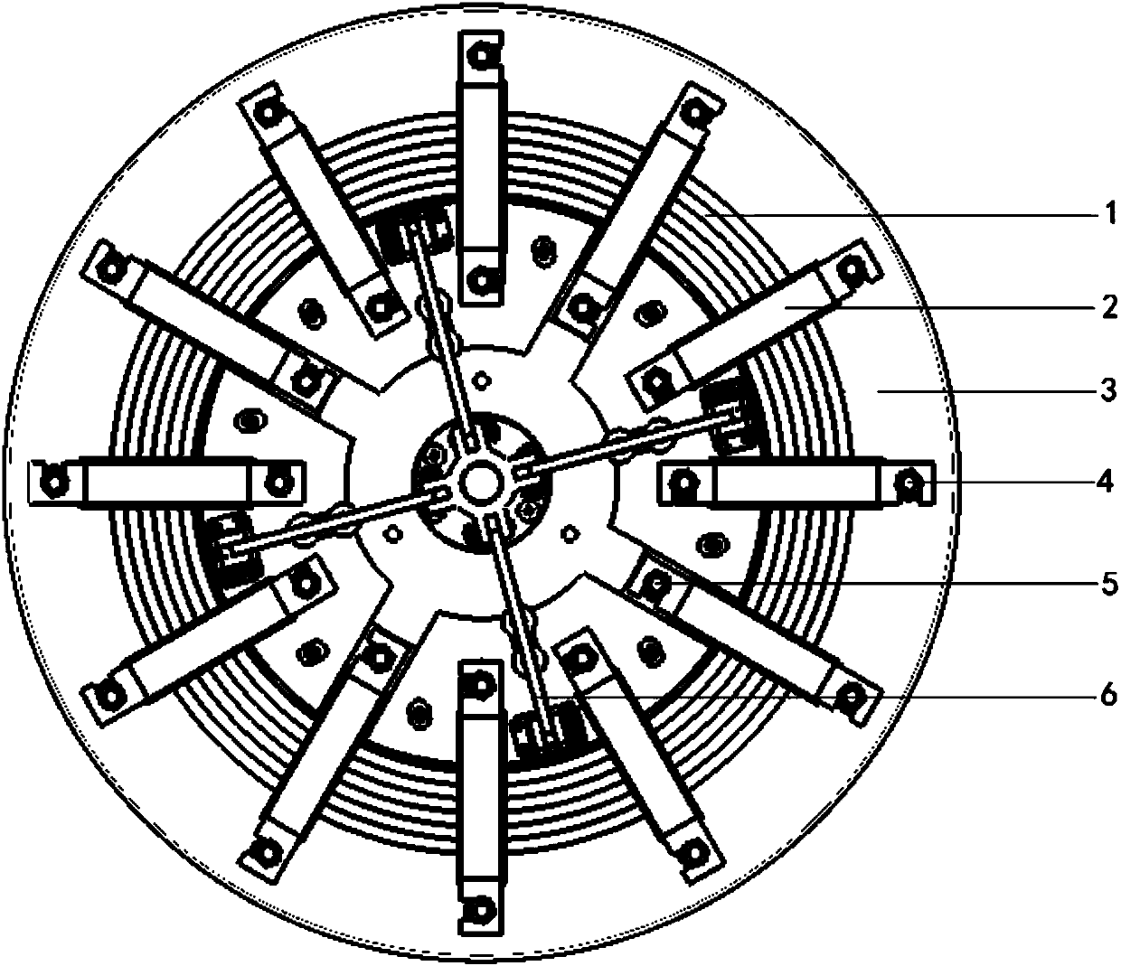
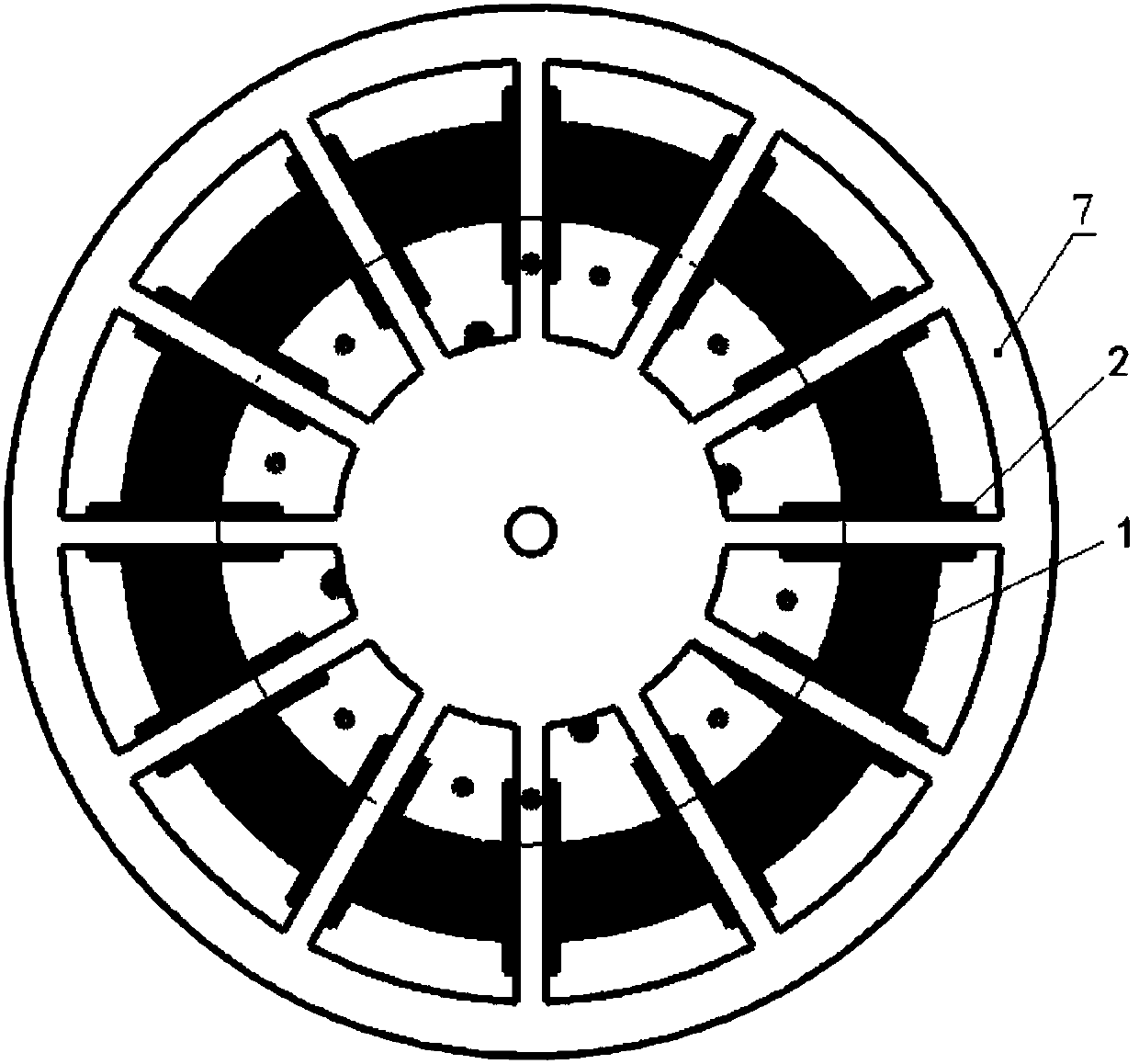
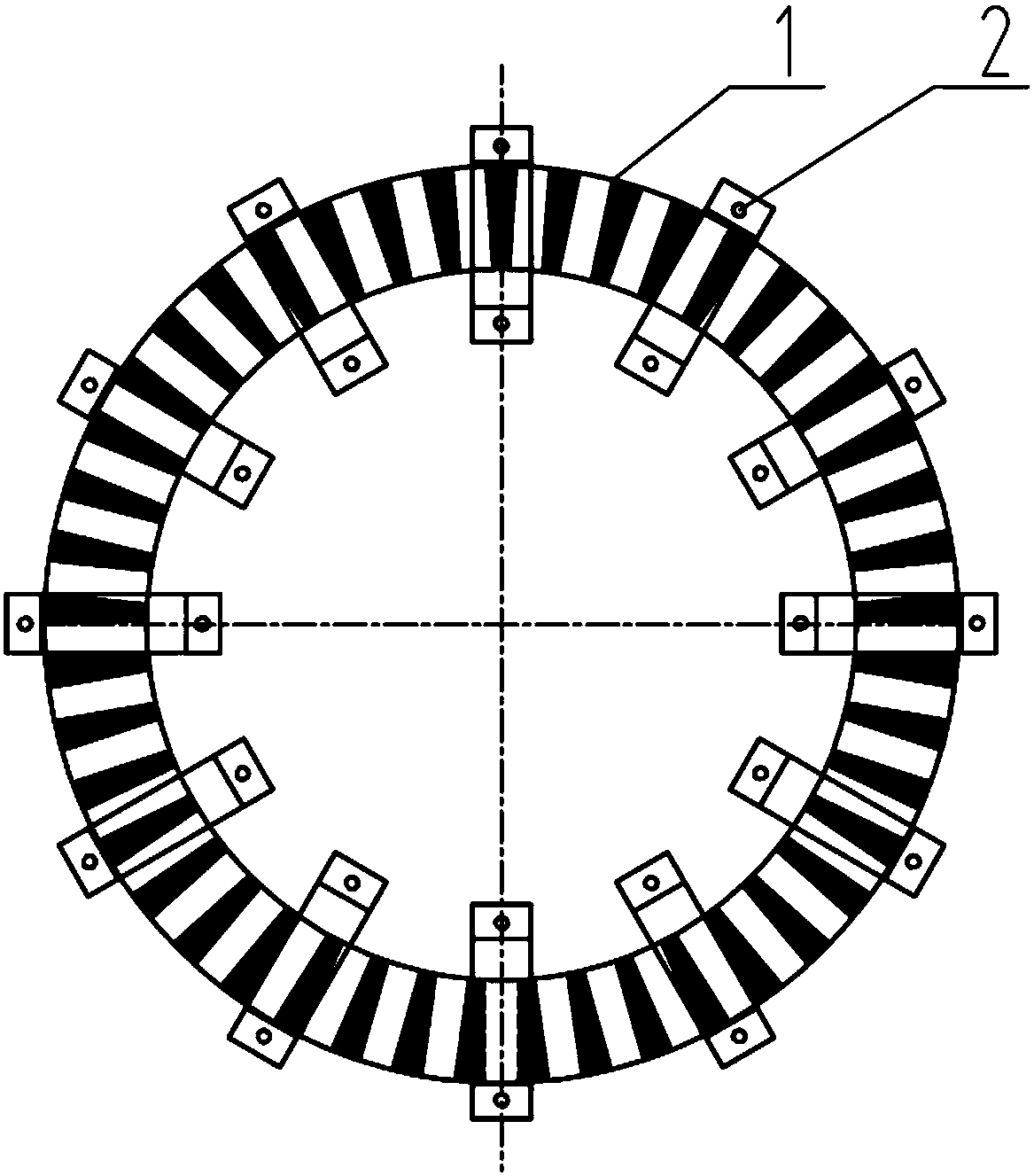
[0029] A disc type stator core welding method by utilizing a welding device such as figure 1 , 2 As shown, the welding device includes a disc-shaped welding platform 3 with a round hole in the middle, a supporting circle assembly 6 matched with the welding platform 3, and an integral locking and pressing assembly 7. The welding platform 3 is provided with a positioning cone 4 and a connecting plate The positioning column 5 and the surface of the welding platform 3 have an inclination of 0.5-5° from the center to the outside, and the overall locking and pressing assembly 7 is in the shape of a steering wheel, and has the same inclination as the surface of the welding platform 3 from the center to the outside. The positioning cones 4 are arranged on the welding platform 3 in a ring shape, the diameter of the ring is the maximum value of the outer circle of the stator core, and the shape of the positioning cones 4 is conical. The connecting plate positioning columns 5 are arrang...


PUM

PropertyMeasurementUnit
angleaaaaaaaaaa

Abstract

The invention relates to a disk type stator iron core welding method. Welding is performed by adopting a welding device, and the welding device comprises a welding platform, a circle expanding assembly and an overall locking compressing assembly; and a positioning cone and connection plate positioning columns are arranged on the welding platform. Specific steps include that (1) a stator iron coreis placed on the welding platform, and the outer circle of the stator iron core is tightly close to the positioning cone to be placed; (2) the circle expanding assembly is adjusted to the limited size, and is put away after being used for performing circle expanding on the inner circle of the stator iron core; (3) threaded holes of a stator iron core connection plate are aligned with the connection plate positioning columns one by one; (4) the overall locking compressing assembly is placed to compress the stator iron core connection plate, and then welding is performed; and (5) the overall locking compressing assembly is removed, cooling is performed, and stator iron core welding is completed. Compared with the prior art, the process is adopted, it is guaranteed that connection plate welding is firm and small in deformation, it is not needed to use stress eliminating equipment or device after welding, and the stator iron core planeness is good.

Description

technical field [0001] The invention relates to the technical field of disc stator cores, in particular to a welding method for disc stator cores. Background technique [0002] The stator of the disc motor uses multiple (8-16) connecting plates to connect with the machine base, so the flatness of the installation plane composed of multiple connecting plates is very high, and the welding quality of the stator core is also relatively high. It is reflected in the small amount of welding deformation, firm welding and good welding appearance. Therefore, the manufacturing process method and process stability of the stator core of the disc motor are very high. The production process of the stator core of the disc motor involves multiple processes, and the whole process is interlocking. If the control is not proper, it may lead to uneven winding of the stator core of the disc motor, large burrs of the iron core, distortion of the stator groove, iron After the core is welded, the de...

Claims


Application Information

Patent Timeline
Patent Type & Authority Applications(China)
IPC IPC(8): B23K9/16B23K9/00
Inventor 顾涛荣叶丽花
Owner 上海华银电器有限公司
Why Eureka
Try Eureka