Steel rail expansion adjuster

A regulator and rail technology, which is applied to rail joints, rails, switches, etc., can solve the problems affecting the normal expansion and contraction of the basic rail of the regulator, the expansion resistance of the basic rail does not drop but rises, and the longitudinal expansion resistance is reduced. Avoiding the overrun of gauge expansion, simple and feasible processing and manufacturing, and reducing the effect of longitudinal expansion resistance

Active Publication Date: 2012-06-27
CHINA RAILWAY BAOJI BRIDGE GRP
View PDF10 Cites 10 Cited by
  • Summary
  • Abstract
  • Description
  • Claims
  • Application Information

AI Technical Summary

Problems solved by technology

The regulator already has the characteristics of safety, smoothness and stability, but after years of operation practice, it has been proved that there are still the following problems: First, the structure design of the backing plate is complicated, there are many parts, and it is very difficult to manufacture in the factory and maintain on site; Second, as one of the key parts, the rail brace is required to achieve "a 2mm clearance from the bottom of the rail" in both in-plant manufacturing and on-site maintenance. However, it is difficult to "reserve a 2mm clearance" in in-plant manufacturing and actual operation. As a result, the telescopic resistance of the basic rail does not decrease but rises; the third is that after long-term operation, the "reserved gap" is often filled with sludge, dirt, and sand in sandy areas, which is difficult to remove in later maintenance. When affecting the normal expansion and contraction of the basic rail of the regulator
In addition, in order to reduce the longitudinal expansion and contraction resistance, there is no rubber backing plate under the basic rail, which will affect the smoothness of the rail

Method used


Image

  • Steel rail expansion adjuster
  • Steel rail expansion adjuster
  • Steel rail expansion adjuster

Examples


Embodiment Construction

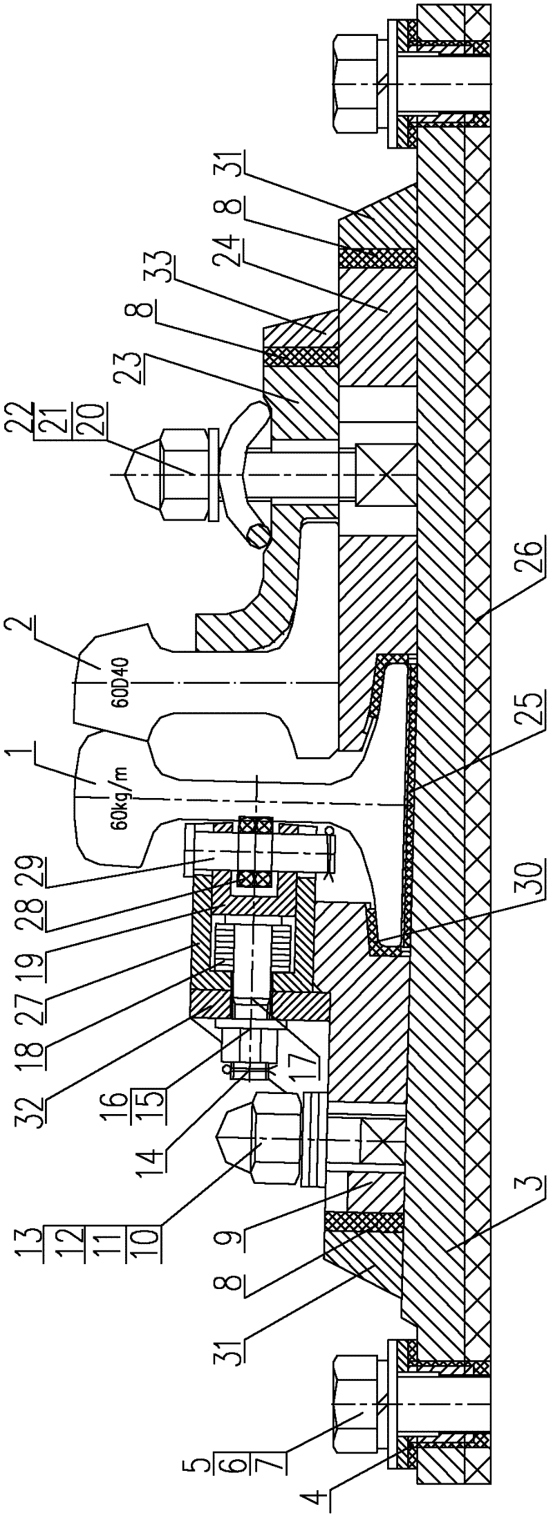
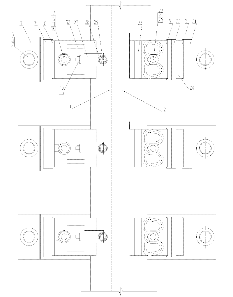
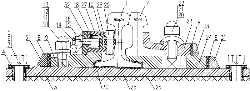
[0020] Attached below figure 1 , 2 An embodiment of the present invention is described.

[0021] A rail telescopic adjuster, which has a basic rail 1 and a point rail 2 arranged inside the basic rail 1, the basic rail 1 is located on an iron backing plate 3, and the iron backing plate 3 is passed through a switch sleeper bolt 5, a spring washer 6, a flat Washer 7 and rubber pad 26 under the board are fixed on the switch sleeper. The switch rail 2 is located on the switch rail platform assembly 24 , and the switch rail platform assembly 24 is located on the iron backing plate 3 . The basic rail 1 is fixedly buckled and pressed on the iron backing plate 3 through the basic rail buckle assembly 9 and the switch rail platform assembly 24, and the inside and bottom of the basic rail buckle assembly 9 and the switch rail platform assembly 24 are inlaid and fixed with anti-friction Fasteners 30, and the wear-reducing fasteners 30 are tightly pressed on the rail limbs on both sides...


PUM


Abstract

The invention relates to a steel rail expansion adjuster, which comprises a basic rail and a sharp rail arranged on the inner side of the basic rail, wherein the basic rail is arranged on an iron base plate which is fixed on a switch sleeper, the sharp rail is arranged on a bedplate assembly of the sharp rail and the bedplate assembly of the sharp rail is arranged on the iron base plate; the basic rail is fixedly buckled and pressed on the iron base plate through a buckle assembly of the basic rail and the bedplate assembly of the sharp rail, and the sharp rail is fixedly buckled and pressed on the bedplate assembly of the sharp rail through a buckle of the sharp rail; and an external frame internally provided with a horizontal guide rod and an internal frame is fixed in an upper position on the inner side of the buckle assembly of the basic rail, the inner side of the internal frame is horizontally provided with a rolling bearing through a pin shaft, and a spring is sleeved on the guide rod so that the internal end face of the guide rod is propped on the external end face of the internal frame, and accordingly, the rolling bearing is supported on the rail web outside the basic rail. The steel rail expansion adjuster disclosed by the invention has the advantages of a simple structure, convenience in manufacturing and maintenance, and capabilities of minimizing the expansion resistance of the basic rail, optimizing the stiffness of switch zone and prolonging the service time of the adjuster on the steel rail.

Description

technical field [0001] The invention belongs to the technical field of railway turnouts, and in particular relates to a rail expansion regulator. Background technique [0002] The rail telescopic adjuster is one of the indispensable track equipment on long-span steel girder bridges and high masonry bridges with seamless lines. The telescopic displacement of the beam end and the long steel rail caused by the temperature difference can dissipate the temperature force of the seamless line on the bridge, thereby reducing the longitudinal force of the seamless line on the track and the pier itself. [0003] The double-track backing plates of the currently used rail telescopic regulators all adopt a double-rail support "reserved gap" structure. The basic rail is flexible and bendable, and the rail support is set on the outer side according to the radius of the circular curve. The basic rail support does not buckle the rail bottom (with a 2mm gap with the rail bottom), but only ti...

Claims


Application Information

Patent Timeline
Patent Type & Authority Applications(China)
IPC IPC(8): E01B11/42E01B7/08E01B9/44E01D19/12
Inventor 董彦录张海华费维周侯小康
Owner CHINA RAILWAY BAOJI BRIDGE GRP
Why Eureka
Try Eureka