
A manufacturing method and structure of a power device terminal ring

A technology for power devices and manufacturing methods, applied in the field of manufacturing methods and structures of power device terminal rings, capable of solving problems such as fluctuations in device parameters, achieving the effects of increasing robustness, reducing fluctuations, and avoiding damage

Active Publication Date: 2014-10-22
HANGZHOU SILAN INTEGRATED CIRCUIT
View PDF3 Cites 2 Cited by
  • Summary
  • Abstract
  • Description
  • Claims
  • Application Information

AI Technical Summary

Problems solved by technology

On the other hand, there are still problems in the actual implementation process, and it is urgent to introduce new methods that can effectively improve the above-mentioned defects to solve the problem that the above-mentioned basic parameters in the existing terminal protection structure with terminal rings are easily affected by fluctuations in the manufacturing process. The main problem is the fluctuation of device parameters from

Method used


Image

  • A manufacturing method and structure of a power device terminal ring
  • A manufacturing method and structure of a power device terminal ring
  • A manufacturing method and structure of a power device terminal ring

Examples


Embodiment Construction

[0020] In order to make the above objects, features and advantages of the present invention more comprehensible, specific implementations of the present invention will be described in detail below in conjunction with the accompanying drawings.

[0021] In the following description, numerous specific details are set forth in order to provide a thorough understanding of the present invention. However, the present invention can be implemented in many other ways different from those described here, and those skilled in the art can make similar extensions without violating the connotation of the present invention, so the present invention is not limited by the specific implementations disclosed below.

[0022] Secondly, the present invention is described in detail using schematic diagrams. When describing the embodiments of the present invention in detail, for the convenience of explanation, the cross-sectional view showing the device structure will not be partially enlarged accordi...


PUM


Abstract

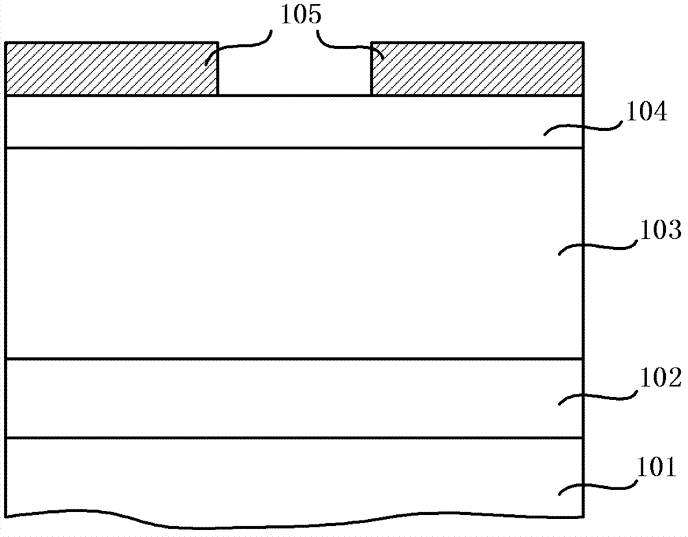
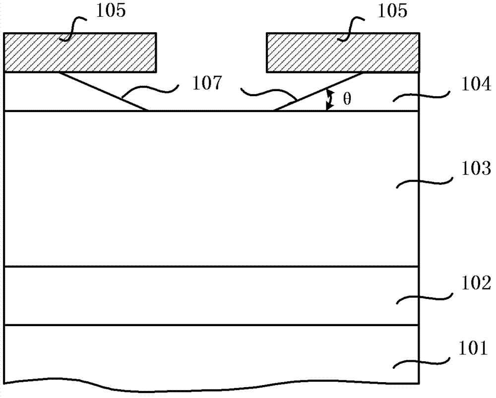
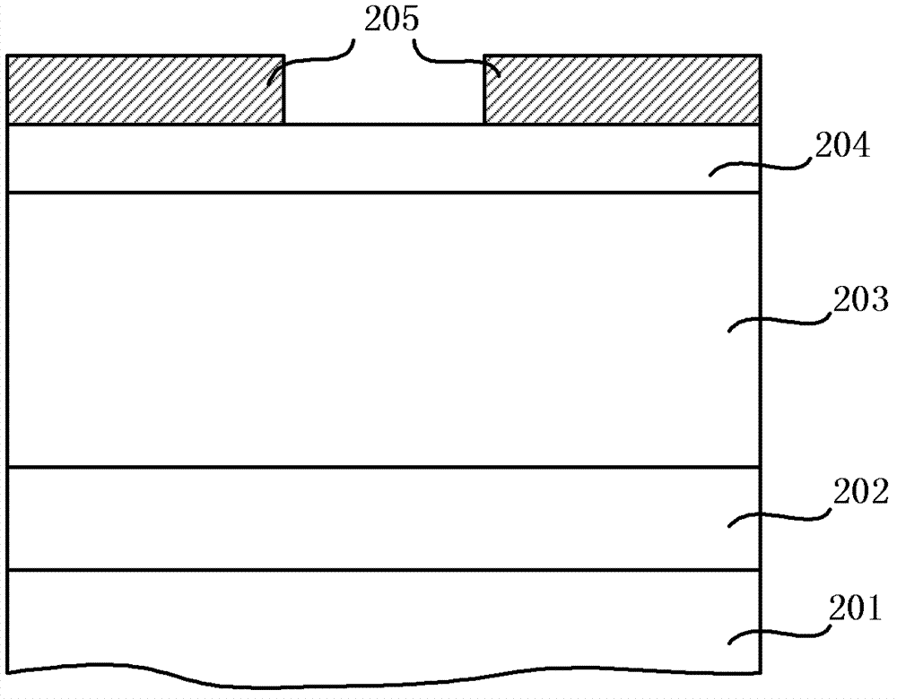
The invention provides a production method for a power device terminal ring, which comprises the following steps: a silicon substrate and a field oxidizing layer of the power device are sequentially arranged on a semiconductor substrate from down to up; a terminal ring photolithographic window is formed in the mask layer of the field oxidizing layer through photolithographic technology; part thickness of the field oxidizing layer in the terminal ring photolithographic window is etched through dry etching, thereby forming a first terminal ring window; the field oxidizing layer in the first terminal ring window is subjected to wet etching, thereby forming a second terminal ring window; the mask layer is removed; the second terminal ring window is not subjected to annealing technology before boron ions are injected; and the terminal ring is formed on the silicon substrate of the power device. A power device terminal ring further provided by the invention is formed through the combination of the dry etching and wet etching, solves the problem that a traditional manufacturing technique adopting either the dry etching or wet etching to form the terminal ring in the field oxidizing layer is unstable, improves the reliability of the product, has strong technical robustness, and is suitable for mass production.

Description

technical field [0001] The invention belongs to the field of power semiconductor device manufacturing, and in particular relates to a manufacturing method and structure of a power device terminal ring. Background technique [0002] With the development of integrated circuits, modern high-voltage power semiconductor devices, insulated gate bipolar transistors (IGBTs), which are third-generation power electronics products, combine the high current density characteristics of insulated gate MOS transistors and bipolar transistors. , and the substantial reduction of the on-resistance provides room for the IGBT to reasonably and effectively increase the withstand voltage. The withstand voltage is an important parameter of the IGBT, and an important precondition to ensure that the IGBT can obtain a higher withstand voltage is that the IGBT device must have an excellent terminal protection structure, so the research on its high-voltage terminal protection structure has always been r...

Claims


Application Information

Patent Timeline
Patent Type & Authority Patents(China)
IPC IPC(8): H01L21/331H01L21/311H01L29/739
Inventor 闻永祥顾悦吉刘琛刘慧勇
Owner HANGZHOU SILAN INTEGRATED CIRCUIT
Learn More