
Phased array antenna with reconstructible directional diagram

A phased array antenna and directional pattern technology, which is applied to antennas, antenna arrays, antenna grounding devices, etc., can solve the problems of insufficient compact structure, low phased array antenna gain, and unit spacing can not be too close, so as to achieve size reduction, The effect of improving array performance and increasing reuse

Inactive Publication Date: 2012-06-27
UNIV OF ELECTRONICS SCI & TECH OF CHINA
View PDF5 Cites 17 Cited by
  • Summary
  • Abstract
  • Description
  • Claims
  • Application Information

AI Technical Summary

Problems solved by technology

The gain of the phased array antenna is low; each array unit has its own different floor, the unit spacing should not be too close, and the structure is not compact enough

Method used


Image

  • Phased array antenna with reconstructible directional diagram
  • Phased array antenna with reconstructible directional diagram
  • Phased array antenna with reconstructible directional diagram

Examples


Embodiment Construction

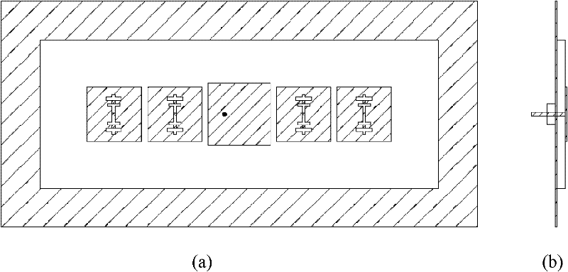
[0024] A phased array antenna with reconfigurable pattern, such as image 3 As shown, at least the following linear phased array antenna is included. The linear phased array antenna includes a dielectric substrate, a metal ground plate and a radiation patch. The dielectric substrate is a rectangular dielectric substrate, and the metal ground plate covers the entire back of the dielectric substrate; the radiation patch is located on the front of the dielectric substrate, and consists of L excitation patches and L+3 parasitic patches, L≥2. The excitation patches are evenly distributed, one parasitic patch is arranged between every two adjacent excitation patches, and two parasitic patches are arranged outside the two excitation patches on the left and right sides. All the stimulus patches are rectangular in shape and have the same size; all the parasitic patches are rectangular in shape and have the same size; the size of the stimulus patch is larger than that of the parasitic ...


PUM


Abstract

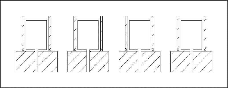
The invention provides a phased array antenna with a reconstructible directional diagram, belonging to the communication technology field, and relating to an antenna structure. The phased array antenna at least comprises a following line style phased array: the line style phased array comprises a medium substrate, a metal ground plate and a radiation patch, the radiation patch is formed by L excitation patches and L+3 parasitic patches, L is larger than or equal to 2, a parasitic patch is arranged between each two adjacent excitation patches, outboards of two excitation patches at left and right sides also are provided with two parasitic patches, a central position of each parasitic patch is opened with a vertical seam and four transverse seams which are crossed with the vertical seam, and the vertical seam is uniformly provided with three switches which are connected with parasitic patches at two sides of the vertical seam. According to the invention, a patch Yagi antenna unit with a reconstructible directional diagram is employed to form a phased array, through compressing the quantity of the parasitic patches of a reconstructible unit, the parasitic patches are combined with different excitation patches in different states, a dimension of the whole array is reduced to a large extent, an array sidelobe level is reduced, and a wave beam scanning scope is enlarged.

Description

technical field [0001] The invention belongs to the technical field of communication, and relates to an antenna structure, in particular to a phased array antenna with a reconfigurable pattern. Background technique [0002] Several antennas are arranged in space and connected to each other to produce a directional pattern. This structure of multiple radiation elements is called an antenna array. If the phase of the excitation current of each unit antenna in the array is changed, the radiation pattern can be scanned in space, which is a phased antenna array. The concept of phased antenna array originated in 1889, and the first binary receiving array was successfully deployed in 1906. It developed vigorously in the 1920s and has been widely used so far. Changing the radiation pattern of the antenna can avoid noise sources or electronic interference, improve communication quality and security, and save energy by aligning signals to users who need to communicate. Therefore, in...

Claims


Application Information

Patent Timeline
Patent Type & Authority Applications(China)
IPC IPC(8): H01Q1/38H01Q1/48H01Q21/00
Inventor 杨雪松张建王秉中
Owner UNIV OF ELECTRONICS SCI & TECH OF CHINA
Learn More