
Hydrothermal ageing device for multi-sample parallel catalyst

A technology of hydrothermal aging and catalyst, applied in the direction of catalyst activation/preparation, physical/chemical process catalyst, chemical instruments and methods, etc., can solve the problems of affecting repeatability, affecting steam distribution, inconsistent catalyst flow state, etc., and achieving good repeatability stability and stability, ensure parallelism and repeatability, save the effect of steam generators

Active Publication Date: 2013-09-18
迈瑞尔实验设备(上海)有限公司
View PDF3 Cites 2 Cited by
  • Summary
  • Abstract
  • Description
  • Claims
  • Application Information

AI Technical Summary

Problems solved by technology

However, both patents need to be improved. The former is affected by the manufacturing accuracy of the sample cups and the stacking state of the catalysts in each sample cup, so the amount of water vapor passing through each sample cannot be precisely controlled; all sample cups rotate on one axis. , may cause mutual contamination of the catalyst; and the rotating mechanism is prone to mechanical failure
Although the latter avoids the mechanical rotation structure and solves the problems of the former, the fluidized solid dust and catalyst dust in the heating furnace are easy to be strung into the aging tube to pollute the catalyst; a large amount of fluidized furnace gas and water vapor entrained dust is easy to cause The filter of the outlet pipe is blocked, which affects the aging pressure; the position of the water vapor entering the pipe in the aging pipe may affect the distribution of the steam, resulting in inconsistent flow state of the catalyst and affecting the repeatability; each aging pipe needs to be equipped with a steam generator; All aging tubes are immersed in the fluidized furnace, which is inconvenient for the catalyst to cool down quickly

Method used


Image

  • Hydrothermal ageing device for multi-sample parallel catalyst

Examples


Embodiment Construction

[0015] In order to make the present invention more comprehensible, preferred embodiments are described in detail below with accompanying drawings.

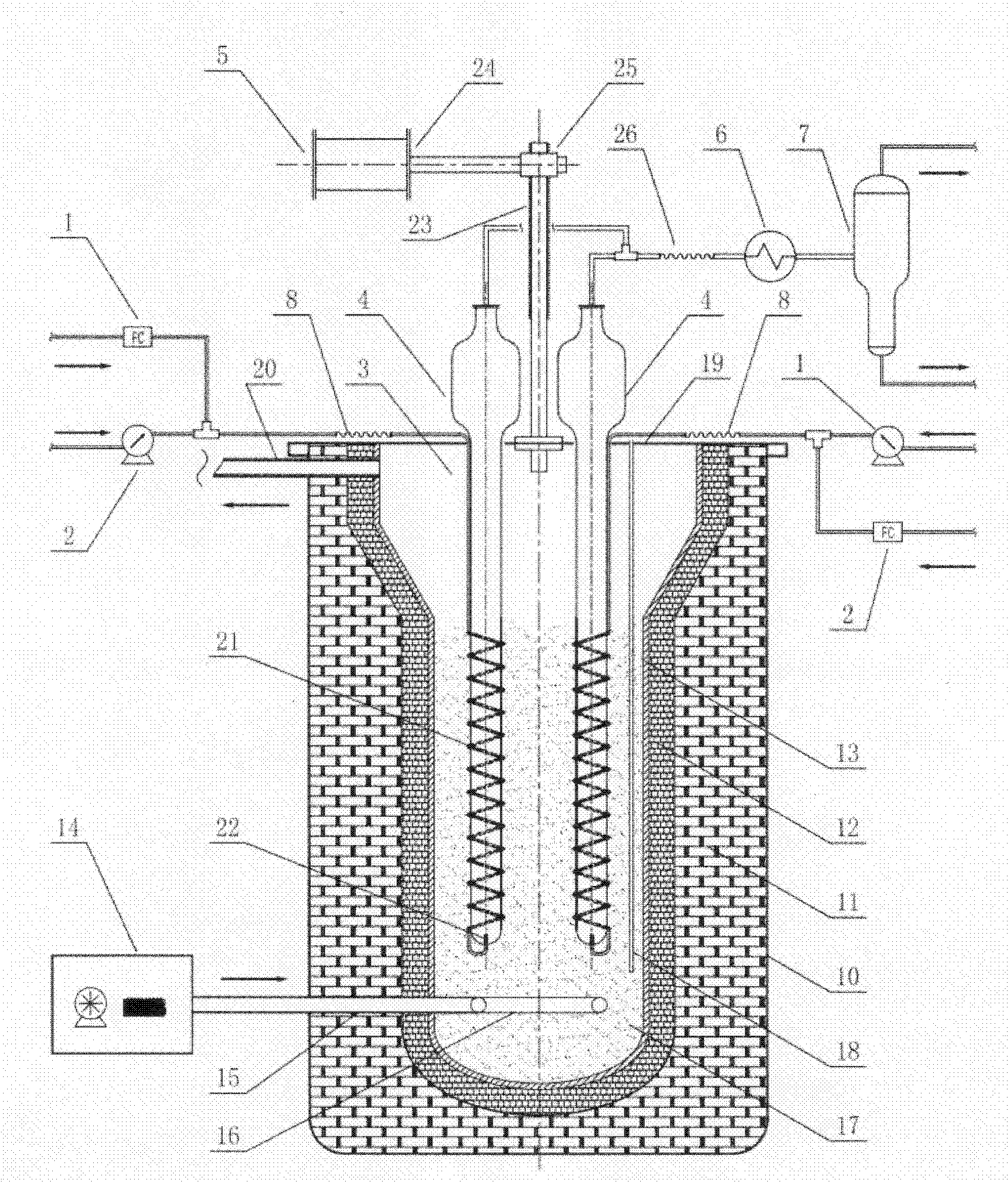
[0016] Such as figure 1 As shown, the key components of a multi-sample parallel catalyst hydrothermal aging device provided by the present invention include: water feed pump 1, gas flow controller 2, sand bath heating system 3, hydrothermal aging reactor 4, reactor lifting Mechanism 5, tail gas cooler 6 and gas-liquid separation tank 7.

[0017] The circumference of the hydrothermal aging reactor 4 is evenly arranged in the sand bath furnace of the sand bath heating system 3, the settling section of the hydrothermal aging reactor 4 is exposed to the sand bath furnace, and its fluidized section is immersed in the quartz sand 17 of the sand bath furnace, Each hydrothermal aging reactor 4 is transported fluidized medium and gas by independent water feed pump 1 and gas flow controller 2 respectively, and all hydrothermal aging reacto...


PUM


Abstract

The invention provides a hydrothermal ageing device for multi-sample parallel catalyst which is characterized by comprising a sand bath heating system, wherein the circumstances of hydrothermal ageing reactors are evenly arranged in the sand bath furnace of the sand bath heating system; the sedimentation section of each hydrothermal ageing reactor is exposed out of the sand bath furnace; the fluidization section of the hydrothermal ageing reactor is dipped in the quartz sand of the sand bath furnace; each hydrothermal ageing reactor conveys a fluidizing medium and gas respectively by virtue of an independent water feeding pump and a gas flow controller; all hydrothermal ageing reactors are lifted or lowered by a reactor lifting mechanism; the waste gas outlets of the sedimentation sections of the hydrothermal ageing reactors are all connected with a tail gas cooler; and the tail gas cooler is connected with a separation tank. Comprehensively, the hydrothermal ageing device can realize the purpose that multiple reactors are operated in parallel under the working condition of consistent ageing condition; and the hydrothermal ageing device is good in repeatability and stability and can be widely applied to the hydrothermal processing experiment of the catalyst.

Description

technical field [0001] The invention relates to a multi-sample parallel catalyst hydrothermal aging device, which is used for simultaneous hydrothermal treatment of multiple samples in a laboratory. Background technique [0002] The activity of catalysts in industrial devices can be dynamically stabilized within a fixed activity range with long-term operation. However, fresh catalysts are unrepresentative due to their high initial activity and instability due to no deactivation process, such as catalytic cracking catalysts. If a fresh catalyst is evaluated in the laboratory, it is necessary to manually reduce the activity of the catalyst to the activity range of the industrial equilibrium catalyst, but the deactivation of the catalyst in the industrial device is a slow process, and the laboratory research needs to quickly reduce the catalyst The activity is reduced, usually by hydrothermal treatment of the catalyst under highly severe conditions. That is, the catalyst is f...

Claims


Application Information

Patent Timeline
Patent Type & Authority Patents(China)
IPC IPC(8): B01J37/10
Inventor 程俊
Owner 迈瑞尔实验设备(上海)有限公司
Learn More