
Autoclave molding method and autoclave molding apparatus

A molding method and molding device technology, applied in the direction of pressure vessels used in chemical processes, can solve problems such as difficulties, achieve the effects of reducing equipment costs, preventing uneven preparation, and reducing curing time

Inactive Publication Date: 2012-07-04
ASHIDA MFG
View PDF4 Cites 8 Cited by
  • Summary
  • Abstract
  • Description
  • Claims
  • Application Information

AI Technical Summary

Problems solved by technology

In addition, the gas must be circulated at a preferred flow rate to allow uniform contact of the heating gas with the composite material, which is difficult

Method used


Image

  • Autoclave molding method and autoclave molding apparatus
  • Autoclave molding method and autoclave molding apparatus
  • Autoclave molding method and autoclave molding apparatus

Examples


Embodiment approach 1

[0066] Preferred embodiments of the autoclave forming method and the apparatus used for the method of the present invention will be described in detail below based on the accompanying drawings. In the first embodiment, a thermosetting resin is used as the matrix.

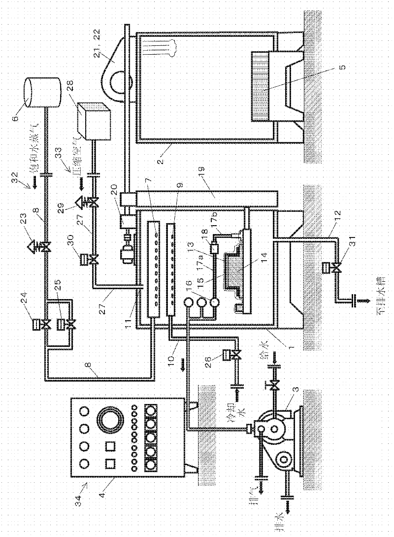
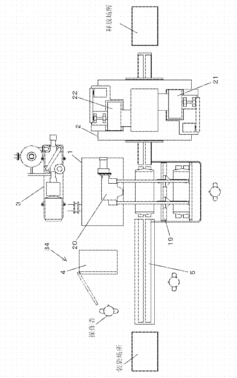
[0067] exist figure 1 with 2 A schematic structure is shown in to show the whole autoclave apparatus of the present invention.

[0068] The device mainly includes a molding chamber 1, a drying chamber 2, a water-sealed vacuum pump 3, a control panel 4, an automatic conveying line 5, that is, a conveyor, a boiler 6, pipelines connected thereto, and a plurality of valves. The detailed structures of these are described below.

[0069] That is, the autoclave molding apparatus forms the composite material 13 by placing it in the vacuum bag 15, then placing it in the molding chamber 1, and heating and pressurizing it. The composite material 13 is obtained by impregnating a fibrous substrate (which in this embodiment ...

example 1

[0109] The above-mentioned Embodiment 1 is partially modified into the form of another embodiment of the present invention (described below).

[0110] Image 6 A schematic diagram of the air nozzle showing another form of the main part of the autoclave apparatus of the present invention is shown. A plurality of nozzles 7 for supplying saturated water vapor into the molding chamber 1 also serve as nozzles 11 for supplying compressed air, which are arranged at the upper portion of the molding chamber 1 in the above-described embodiment. Therefore, compressed air is showered onto the vacuum bag 15 in a similar manner to saturated water vapor showered onto the vacuum bag 15, and local pressure variations to the composite material 13, ie, the product to be molded, are reduced. Therefore, a stable molded product without process variation can be manufactured.

[0111] in which the number of the member is not stated Image 6 , refer to the description of Embodiment 1 above.

example 2

[0113] Fast curing prepregs can be formed by the method and apparatus of the present invention. The fast-curing prepreg as the composite material 13 contains a thermosetting resin as a matrix that reacts and cures in a short time. The fast curing prepreg may be, for example, Tough-Qure (trade name) manufactured by Mitsubishi Rayon Co., Ltd. In this case, the reaction curing time at 130°C is 30 minutes, whereas in the case of a general prepreg, it is 1 hour at 130°C. In addition, because the saturated water vapor used here has a large amount of heat, the temperature variation is reduced, the curing time is significantly shortened, and the productivity is significantly improved. The shorter the curing time, the less heat energy is discarded, thus saving energy. The advantage of fast cure can be maximized by the reduction of temperature variation.


PUM


Abstract

The invention relates to an autoclave molding method and an autoclave molding apparatus. The composite material formed of a fiber substrate and a matrix is placed in a vacuum bag and then in the molding chamber. Saturated steam of a predetermined temperature needed for the composite material is supplied to the molding chamber, and the temperature and the pressure inside the molding chamber are controlled so that the inside of the molding chamber may be maintained at a predetermined temperature and a predetermined pressure needed for the composite material in order to carry out a curing step.

Description

technical field [0001] The present invention relates to an autoclave forming method and an autoclave forming apparatus for composite material formed products used in aircraft, automobiles and other general industries. Background technique [0002] Shaped products having a desired cross-sectional shape have conventionally been obtained by a known method of heating and pressing forming a sheet-like composite material, ie, a prepreg (prepreg) by using a method called The matrix is ​​prepared by impregnating a thermosetting resin such as epoxy or phenolic resin with a reinforcing material such as carbon fiber, aramid fiber or glass fiber. [0003] These fibers are formed into sheet-like fiber layers. Multiple fiber layers are laminated to form a composite material in such a way that the fibers of the layers are arranged in different directions. By doing so, light-weight and strong products can be obtained because carbon fiber, glass fiber, etc. have a high modulus of elasticit...

Claims


Application Information

Patent Timeline
Patent Type & Authority Applications(China)
IPC IPC(8): B29C70/44B29C70/54B01J3/04
CPCB29C35/049B29C35/007B29C70/44B29C35/0227B29C33/04B29C35/04B29C43/12B29C43/56B29C43/58B29C70/06B29C43/10
Inventor 芦田健
Owner ASHIDA MFG
Learn More