

Chemically mechanical polishing solution
A chemical machinery and polishing liquid technology, applied in polishing compositions containing abrasives, etc., can solve the problems of difficult polysilicon removal, high polysilicon/silicon dioxide selection ratio, and achieve no polysilicon residue, increased productivity, and high flatness. Effect
Inactive Publication Date: 2012-07-04
ANJI MICROELECTRONICS (SHANGHAI) CO LTD
View PDF7 Cites 6 Cited by
- Summary
- Abstract
- Description
- Claims
- Application Information
AI Technical Summary
Problems solved by technology
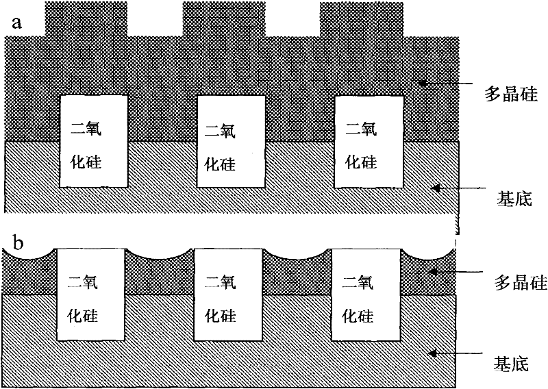
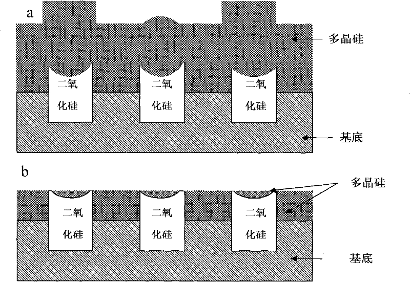
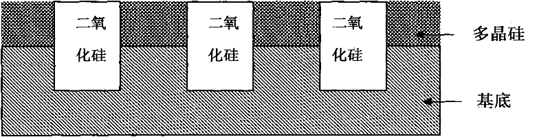
[0008] The purpose of the present invention is to solve the problem that the above-mentioned polysilicon / silicon dioxide selectivity ratio is too high, and the remaining polysilicon in the silicon dioxide butterfly-shaped depression is difficult to remove, and to provide a kind of polysilicon / silicon dioxide with suitable polysilicon for polishing polysilicon CMP
Method used
View moreImage
Smart ImageViewing Examples

Examples
Embodiment 1
[0026] The chemical mechanical polishing fluid of embodiment 1 polysilicon
[0027] Table 1 has provided the formula of polysilicon chemical mechanical polishing liquid 1~35 of the present invention, mixes uniformly by each component and content thereof given in the table, water makes up the percentage by weight to 100%, adopts potassium hydroxide and nitric acid etc. to adjust to The polishing liquid of each embodiment can be prepared at a suitable pH value, and water is the balance.
[0028] Table 1 Chemical Mechanical Polishing Fluids for Polysilicon 1-35
[0029]
[0030]
[0031]
Login to View More PUM
| Property | Measurement | Unit |
|---|---|---|
| particle diameter | aaaaa | aaaaa |
Abstract
The invention discloses a novel chemically mechanical polishing solution for polycrystal silicon. The novel chemically mechanical polishing solution comprises grinding particles, at least one azoles compound and at least one polyalcohol nonionic surfactant. The novel chemically mechanical polishing solution can be used for adjusting the selection rate between the polycrystal silicon and silicon dioxide and remarkably improving the polarization efficiency of the polycrystal silicon.
Description
technical field [0001] The invention relates to a chemical mechanical polishing fluid, in particular to a chemical mechanical polishing fluid for polishing polysilicon. Background technique [0002] In the manufacture of integrated circuits, the standard of interconnect technology is increasing, and layers are deposited on top of each other, resulting in the formation of irregular topography on the substrate surface. A planarization method used in the prior art is chemical mechanical polishing (CMP). The CMP process uses a mixture containing abrasives and a polishing pad to polish the surface of a silicon wafer. In a typical chemical mechanical polishing method, the substrate is placed in direct contact with a rotating polishing pad, applying pressure on the backside of the substrate. During polishing, the pad and stage are rotated while maintaining a downward force on the backside of the substrate to apply an abrasive and chemically active solution (commonly called a polis...
Claims
Login to View More Application Information
Patent Timeline
 Patent Type & AuthorityApplications(China)
IPC IPC(8): C09G1/02
Inventor荆建芬
OwnerANJI MICROELECTRONICS (SHANGHAI) CO LTD