Pitch-based subresolution assist feature design

a subresolution and feature technology, applied in the field of integrated circuit fabrication, can solve the problems of imposing formidable problems, degrading process windows of pitches other than primary pitches, and little improvement of resolution for isolated lines, etc., to achieve fast, cost-effective, and maximum process window

Inactive Publication Date: 2005-11-08
GLOBALFOUNDRIES INC
View PDF37 Cites 26 Cited by
  • Summary
  • Abstract
  • Description
  • Claims
  • Application Information

AI Technical Summary

Benefits of technology

[0012]Thus, there remains a need to provide for a method for implementing sub-resolution assist features in lithographic mask or reticle designs that maximizes process window in a fast, cost-effective manner.

Problems solved by technology

Approaching k1=0.5 imposes formidable problems due to image quality degradation associated with the loss of increasing numbers of diffracted orders.
The drawback of OAI is that,pitches other than the primary pitch will print with degraded process windows.
In addition, since there are no discrete diffracted orders for isolated lines, there is little improvement of resolution for isolated lines as compared to densely pitched lines and spaces.
The resulting pitches P1, P2, P3, and P4 will not typically match the primary pitch P0, and will often result in less than optimal lithographic process windows.
However, even though the placement of assist features 24 and 26 may correspond to P0, using only two SRAFs is typically inadequate to reproduce the interference effect required to obtain an optimal process window.
Such optimization, however, requires very costly and time-consuming theoretical and experimental processes.
Since a typical layout may have several tens or hundreds of possible pitches to evaluate, the empirical evaluation of all combinations quickly becomes impractical.
Furthermore, there are many more possibilities for each parameter, and even this impractically large number of data points represents a sparse sampling for realistic layout configurations.

Method used


Image

  • Pitch-based subresolution assist feature design
  • Pitch-based subresolution assist feature design
  • Pitch-based subresolution assist feature design

Examples


Embodiment Construction

[0046]Reference may now be made to the following detailed description of preferred embodiments of the invention, taken in conjunction with the accompanying drawings, which are not necessarily drawn to scale.

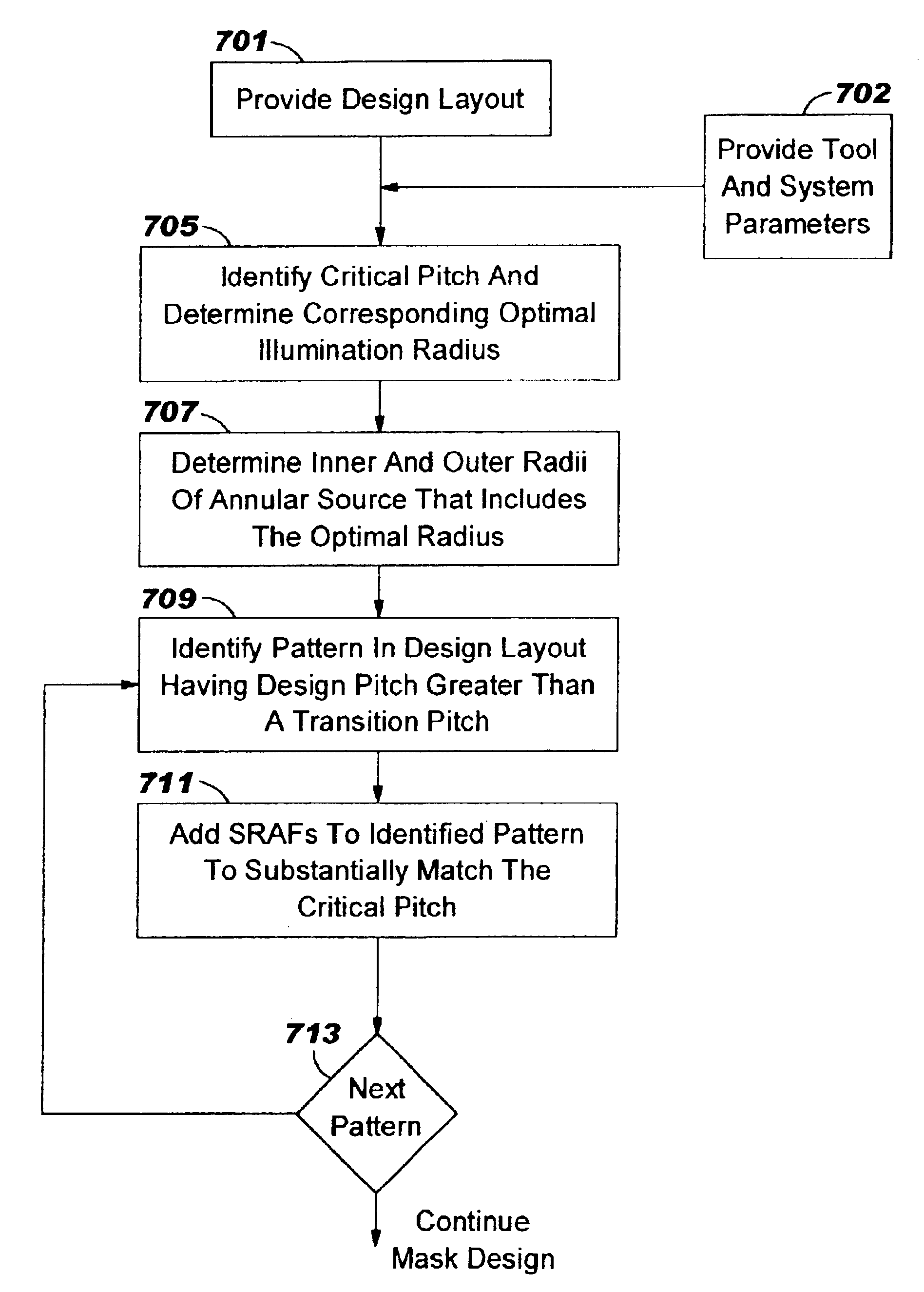
[0047]In accordance with the present invention, a method is provided for designing a lithographic mask for use with a lithographic projection system that has an annular illumination source so that the lithographic process window is optimized. More particularly, a preferred embodiment of the method provides a method for rapidly determining the configuration (for example, the number and spacing) of subresolution assist features (SRAFs), that is matched to the radial coordinates of the annular illumination source that are optimal for critical pitches of the integrated circuit (IC) design layout to be printed.

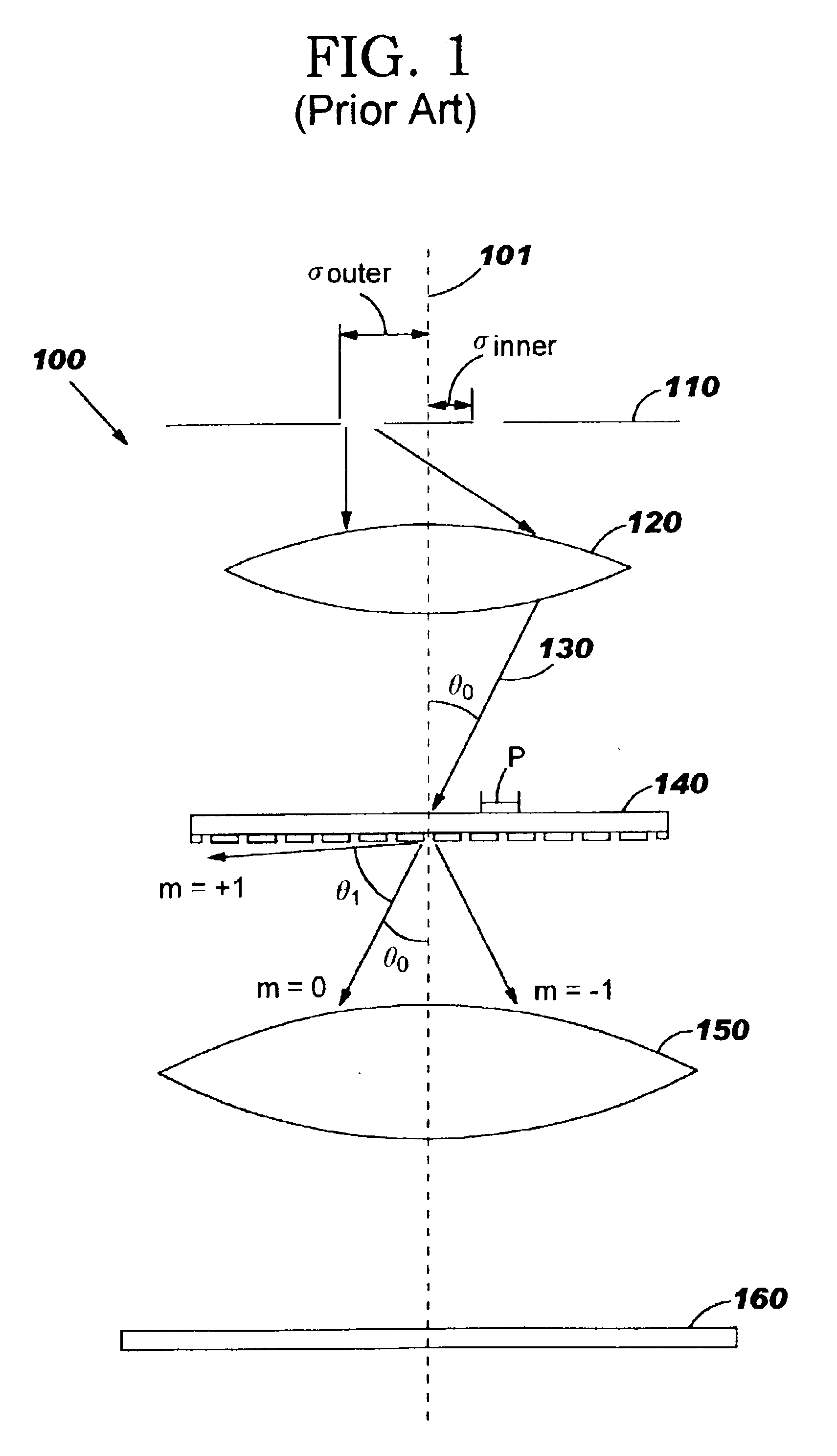
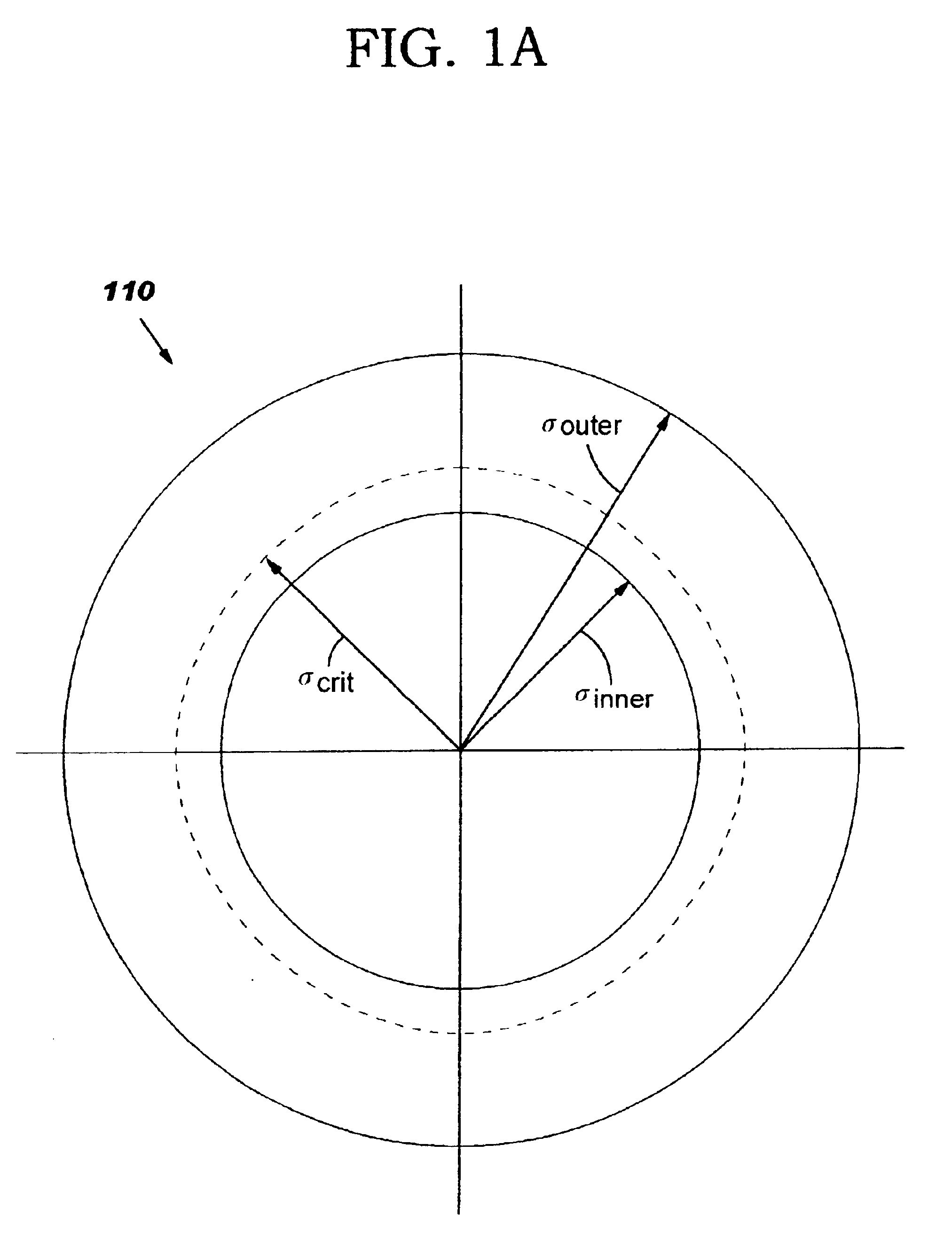
[0048]A lithographic projection system that has an annular illumination source having a radius σ is known to provide a good lithographic process window for a periodic (grating) ...


PUM

PropertyMeasurementUnit
refractive indexaaaaaaaaaa
thresholdaaaaaaaaaa
wavelengthaaaaaaaaaa

Abstract

A method of designing a mask for imaging an integrated circuit (IC) design layout is provided to efficiently configure subresolution assist features (SRAFs) corresponding to an optimally configured annular illumination source of a lithographic projection system. A critical pitch is identified for the IC design, and optimal inner and outer radial coordinates of an annular illumination source are determined so that the resulting image projected through the mask will be optimized for the full range of pitches in the design layout. A relationship is provided for determining an optimal inner radius and outer radius for the annular illumination source. The number and placement of SRAFs are added to the mask design so that the resulting range of pitches substantially correspond to the critical pitch. The method of configuring SRAFs so that the image will have optimal characteristics, such as good contrast and good depth of focus, is fast.

Description

FIELD OF THE INVENTION[0001]The present invention relates, in general, to the fabrication of integrated circuits, and, more particularly, to a method of designing lithographic masks or reticles for use in manufacturing semiconductor devices, and more specifically, for implementing sub-resolution assist features in such lithographic mask or reticle designs.BACKGROUND OF THE INVENTION[0002]There is a continuing effort to reduce the dimensions of integrated circuit (IC) devices, and this has required greater precision in the tools used to manufacture IC devices. IC devices are designed using computer-aided design (CAD) or technology-computer-aided design (TCAD) layout tools which allow designers and manufacturers to plan the layout of circuits on a semiconductor wafer. The finished designs must be transferred to the wafer in a manner that allows device features to be produced by various processes of etching, depositing, implanting, and the like. This is done by applying a photoresist (...

Claims


Application Information

Patent Timeline
Patent Type & Authority Patents(United States)
IPC IPC(8): G03F1/14G03F1/00G06F17/50H01L21/027
CPCG03F1/144G03F7/70125G03F7/70441G06F17/5068G06F2217/12G03F1/36G06F30/39G06F2119/18
Inventor LIEBMANN, LARS W.GABOR, ALLEN H.GORDON, RONALD L.FONSECA, CARLOS A.BURKHARDT, MARTIN
Owner GLOBALFOUNDRIES INC
Why Eureka
Try Eureka