Novel asphalt pavement damage comprehensive intelligent detecting vehicle

An asphalt pavement, intelligent detection technology, applied in the field of traffic engineering, can solve the problems of limited application, inaccurate and low GPS positioning, and achieve the effect of improving detection efficiency

Inactive Publication Date: 2012-07-04
TONGJI UNIV
View PDF5 Cites 13 Cited by
  • Summary
  • Abstract
  • Description
  • Claims
  • Application Information

AI Technical Summary

Problems solved by technology

At present, most laser structured light has the problem that it can only be detected at night or the detection accuracy is not high due to vibration.
In addition, no matter which technology is used, the current detection of road deformation has the problem of ignoring the three-dimensional deformation of the road surface, and the established three-dimensional shape of the road surface cannot accurately reflect the working state of the road surface.
At present, the integrated road surface detection equipment also has the following problems to varying degrees: the damage location technology only uses GPS or only uses the mileage controller, which has the disadvantages of inaccurate GPS positioning and ignoring the overall situation of mileage control; the detection device and the vehicle body are not integrated. Design, it is difficult to ignore the impact of the vibration of the vehicle body or detection device on the detection results during driving
[0004] In view of the above reasons, although a variety of automatic pavement detection equipment based on image processing has come out, its application in actual production practice is still very limited, and there is still a lot of room for research in this field.

Method used


Image

  • Novel asphalt pavement damage comprehensive intelligent detecting vehicle
  • Novel asphalt pavement damage comprehensive intelligent detecting vehicle
  • Novel asphalt pavement damage comprehensive intelligent detecting vehicle

Examples


Embodiment Construction

[0025] The present invention will be further described below in conjunction with the embodiments shown in the accompanying drawings.

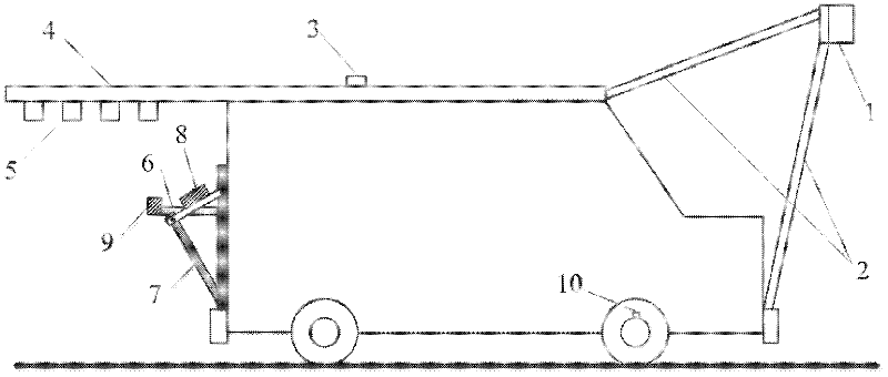
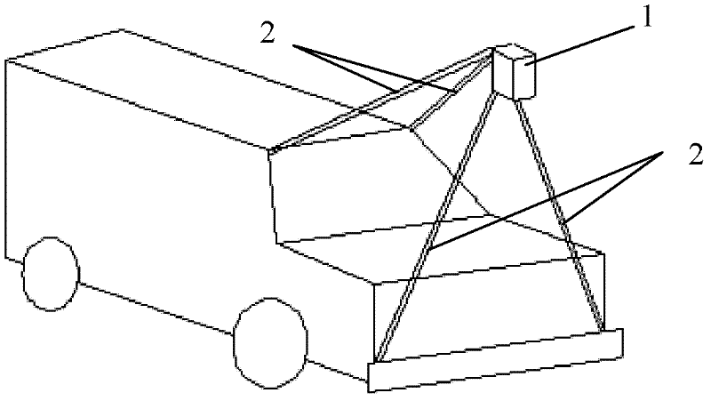
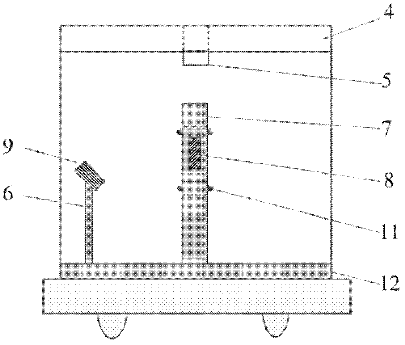
[0026] Such as figure 1 As shown, the integrated intelligent detection vehicle for asphalt pavement damage of the present invention includes a vehicle body, a road surface damage detector 1 , a road surface deformation detector, a GPS device 3 and a mileage distance measuring device 10 . The road surface damage detector 1 is installed on the front end of the vehicle body through the bracket 2; the road surface deformation detector is installed on the rear end of the vehicle body; the GPS device 3 is installed on the top of the vehicle body; the mileage ranging device 10 is installed on the wheel axle of the detection vehicle. The road surface damage detector 1 includes a high-speed high-definition CCD line scan camera 24, an illumination laser 22 and a first prism 23, wherein the first prism 23 is placed in front of the illumination laser 22, a...


PUM

PropertyMeasurementUnit
widthaaaaaaaaaa

Abstract

The invention discloses a novel asphalt pavement damage comprehensive intelligent detecting vehicle which comprises a vehicle body, a pavement damage detecting instrument, a pavement deformation detecting instrument, a GPS (Global Positioning System) device and a mileage distance measuring device, wherein the pavement damage detecting instrument is installed at the front end of the vehicle body and is used for acquiring pavement damage information by shooting pavement images; the pavement deformation detecting instrument is installed at the tail end of the vehicle body and is used for determining pavement deformation information by the deformation of at least three beams of parallel laser rays and at least three beams of laser rays vertical to the parallel laser rays projected on the pavement; the GPS device is installed at the top part of the vehicle body; and the mileage distance measuring device is installed on the wheel shaft of the detecting vehicle. According to the invention, continuous or interval shooting is carried out on the pavement at day and night; a structured light projection principle is used for quickly detecting the three-dimensional deformation of the pavement, and effectively overcoming the interference of sunlight in the daytime; and the pavement damage regions are positioned, the accurate pile number position of the pavement damage relative to a route is obtained, and the damage and deformation data of the asphalt pavement can be simultaneously obtained at a normal running speed.

Description

technical field [0001] The invention belongs to the field of traffic engineering and relates to a road surface detection vehicle, in particular to a detection vehicle aimed at the damage of asphalt pavement. Background technique [0002] With the substantial increase in the mileage of high-grade highways and expressways and the increase in traffic volume year by year, accurate and rapid detection of road damage without disturbing traffic has become an urgent need for road maintenance management. The main damage of asphalt pavement can be divided into surface damage and deformation. The scope and degree of these two types of damage are usually the basis for asphalt pavement maintenance. The pavement testing equipment that has come out or is in the research stage also mainly detects these two types of damage . Among them, non-destructive testing based on image processing technology is an important direction of research in this field, but the current technical level is still n...

Claims


Application Information

Patent Timeline
Patent Type & Authority Applications(China)
IPC IPC(8): E01C23/01G01B11/16G01N21/88
Inventor 陈长孙立军李莉王慧
Owner TONGJI UNIV
Why Eureka
Try Eureka