
High-torque drilling machine with power-shifting gearbox

A power shifting and gearbox technology, applied in the field of high-torque drilling rigs, can solve problems such as difficult meshing, damage, and safety accidents of shifting gears, and achieve the effects of reasonable and compact structure design, simple operation, and good disassembly effect

Inactive Publication Date: 2012-07-04
HANGZHOU XIANGLONG DRILLING EQUIP TECH CO LTD
View PDF11 Cites 10 Cited by
  • Summary
  • Abstract
  • Description
  • Claims
  • Application Information

AI Technical Summary

Problems solved by technology

However, during the actual shifting operation of the gear box of the drilling rig, the relative positions of the teeth and the tooth slots are dislocated and when the shifting is not completed, the rotation of the gears will cause an impact on the meshing action, which makes it difficult to mesh the shifting gears. The bit gears will also be worn or damaged due to the impact. In the process of use, it is often necessary for the operator to have certain operating experience in order to be able to shift gears smoothly.
In addition, due to the narrow and limited space in the coal mine tunnel, the drilling rig can only use short drill pipes to drill holes in the tunnel, which increases the number of drill pipe disassembly. After the drill pipe in the hole operation is subjected to a large torque force, the connection becomes very tight, making it very difficult to disassemble the drill pipe
When the drilling direction of the drilling rig has an upward angle, it is only fixed by the clamping force of the hydraulic chuck. When an emergency occurs, the drill pipe will slide down due to gravity, resulting in a safety accident.

Method used


Image

  • High-torque drilling machine with power-shifting gearbox
  • High-torque drilling machine with power-shifting gearbox
  • High-torque drilling machine with power-shifting gearbox

Examples


Embodiment

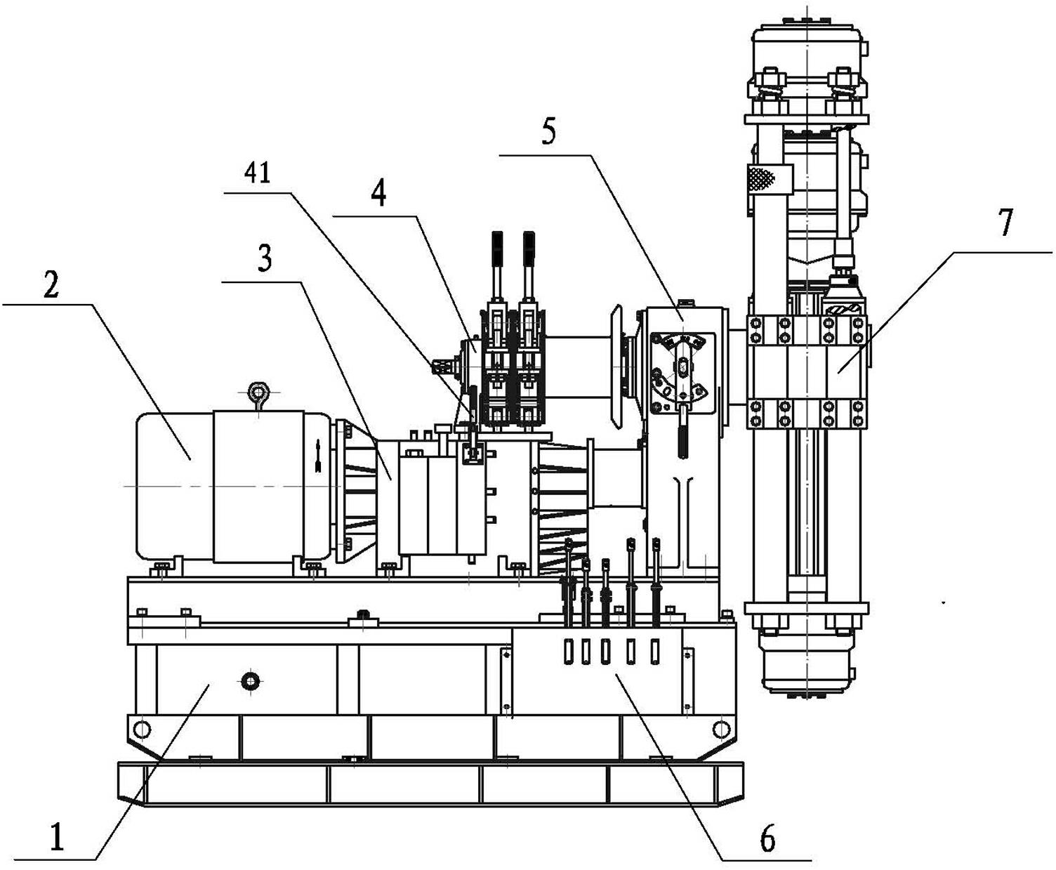
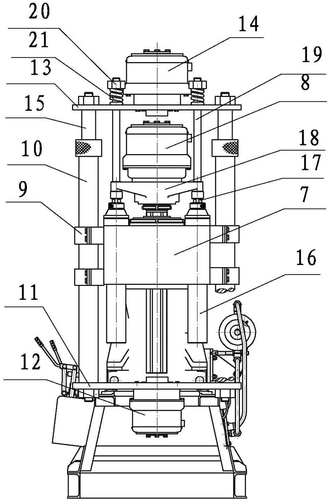
[0016] Example: such as figure 1 , a high-torque drilling rig with a power shift gearbox, including a frame 1, a motor 2, a gearbox 3, a transfer case 5, a winch 4, a gyrator 7 and a control part 6, wherein the gyrator 7 is provided with a piston Cylinder 16, the piston cylinder 16 is provided with a piston rod 17 matched with it, the piston rod 17 is fixed with a beam 18, the beam 18 is provided with a hydraulic chuck 8, and the two sides of the gyrator 7 are provided with four pairs of casing pressure plates 9, A sleeve 10 is fixed inside the sleeve pressure plate 9, a front clamper fixing plate 11 is fixed at the front end of the sleeve sleeve 10, a front clamper 12 is arranged on the front clamper fixing plate 11, and a front clamper 12 is arranged on the front end of the sleeve sleeve 10. Be provided with the slide bar 15 that can slide in sleeve pipe 10, be fixed with post clamper fixed plate 13 on the slide bar 15, be provided with post clamper 14 on the post clamper fi...


PUM


Abstract

The invention relates to a high-torque drilling machine with a power-shifting gearbox. The high-torque drilling machine comprises a machine frame, a motor, a gearbox body, a transfer case, a windlass, a gyrator and a control part, wherein a piston cylinder is arranged on the gyrator; a piston rod matched with the piston cylinder is arranged on the piston cylinder; a cross beam is fixed on the piston rod; a hydraulic chuck is arranged on the cross beam; four pairs of sleeve pressure plates are arranged on two sides of the gyrator; a sleeve is fixed in each sleeve pressure plate; a fixing plate for a front clamp holder is fixed at the front end of the sleeve; the front clamp holder is arranged on the fixing plate; a sliding rod capable of sliding in the sleeve is arranged at the rear end of the sleeve pipe; a fixing plate for a back clamp holder is fixed on the sliding rod; and a rear clamp holder is arranged on the fixing plate for the back clamp holder. The invention has the benefit effects as follows: 1, all gears in the gearbox are in a normally engaged state, so as to avoid damage on the gears caused by mis-operation; 2, a drill rod can be disassembled conveniently and easily without extra manpower; and 3, the front clamp holder can be used for clamping the drill rod tightly when the drilling machine is used for drilling a hole with an elevation angle, so as to prevent the drill rod from falling down, and avoid safety accidents.

Description

technical field [0001] The invention relates to the technical field of mining machinery, in particular to a high-torque drilling rig with a power shift gearbox. Background technique [0002] In coal mine tunnel exploration, the drilling rig needs to face different geological layers, and different speeds must be selected for geological drilling, so as to meet the requirements of geological exploration. The traditional drilling rig is powered by a motor, and the power is transmitted to the gearbox through a dry friction clutch. The gearbox then manually adjusts the meshing of different gears and double sliding gears to achieve the changing speed. However, during the actual shifting operation of the gear box of the drilling rig, the relative positions of the teeth and the tooth slots are dislocated and when the shifting is not completed, the rotation of the gears will cause an impact on the meshing action, which makes it difficult to mesh the shifting gears. The bit gears will...

Claims


Application Information

Patent Timeline
IPC IPC(8): E21B3/02E21B19/10F16H3/02
Inventor 徐鸿祥郑龙
Owner HANGZHOU XIANGLONG DRILLING EQUIP TECH CO LTD
Learn More