
Integrated micro-optics backlight module

A backlight module, micro-optical technology, applied in optics, optical components, light guides, etc., can solve the problem of lack of integration, and achieve the effects of improving brightness and uniformity, improving light energy utilization, and reducing production costs

Inactive Publication Date: 2012-07-04
徐平 +1
View PDF12 Cites 8 Cited by
  • Summary
  • Abstract
  • Description
  • Claims
  • Application Information

AI Technical Summary

Problems solved by technology

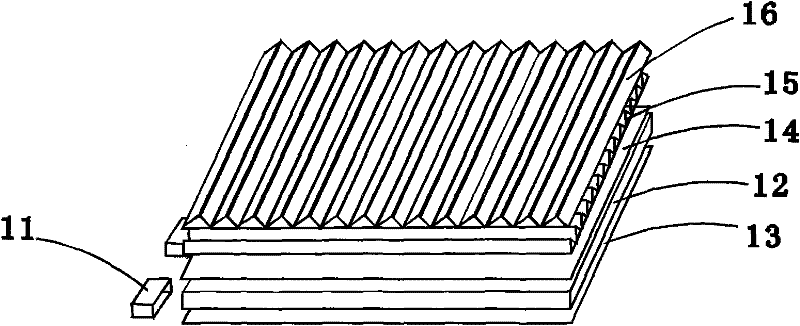
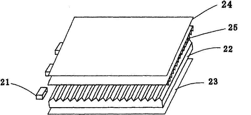
But this backlight module is the same as image 3 The backlight module shown also uses separate reflectors, and does not achieve true integration

Method used


Image

  • Integrated micro-optics backlight module
  • Integrated micro-optics backlight module
  • Integrated micro-optics backlight module

Examples


Embodiment Construction

[0026] The structure of the integrated micro-optical backlight module of the present invention will be further described in detail below in conjunction with the drawings and multiple embodiments.

[0027] Figure 5 It is a structural schematic diagram of the first embodiment of the integrated micro-optical backlight module of the present invention. Please also refer to Figure 5 , Figure 5A, Figure 5B and Figure 5C , the integrated micro-optic backlight module includes: an integrated micro-optic light guide plate 51 and at least one light source 52, the integrated micro-optic light guide plate 51 has a light incident surface 511, a light incident surface 511 connected A light-emitting surface 512, a bottom surface 513 opposite to the light-emitting surface 512, and three sides connecting the light-emitting surface 512 and the bottom surface 513; In the designed aspherical semi-columnar micro-optical light-concentrating structure 5121, a micro-optical prism reflective s...


PUM


Abstract

The invention provides an integrated micro-optics backlight module, which comprises an integrated micro-optics light-guiding plate and at least one light source. The light-guiding plate comprises a light incidence surface, a light emitting surface, a bottom surface opposite to the light emitting surface and three side faces, wherein the three side faces are connected with the light emitting surface and the bottom surface, a micro-optics light condensing structure designed by utilizing micro-optics and binary optic iterative algorithm is arranged on the light emitting surface, and a micro-optics reflection structure matched with the micro-optics light condensing structure on the light emitting surface is arranged on the bottom surface. The micro-optics reflection structure on the bottom surface can reflect and diffract light beams, and the micro-optics light condensing structure on the light emitting surface is matched with the micro-optics reflection structure on the bottom surface so that the light beams can be concentrated in an ideal view field to be emitted, and radiance and uniformity of emitted light are improved. The integrated micro-optics backlight module does not use a flat surface reflective sheet, a diffusing sheet and a double-layer crossed-prism lens in a typical backlight module but exceeds a typical multiple-layer structure in effect, the backlight module is highly integrated, utility rate of luminous energy is improved, and cost is reduced.

Description

【Technical field】 [0001] The invention relates to an integrated micro-optical backlight module used for passive luminescent small and medium size flat panel displays. 【Background technique】 [0002] In recent years, with the development of display technology, especially the liquid crystal display device has the advantages of light weight, thin thickness, high light energy utilization rate, no radiation, etc., the traditional cathode ray display device is gradually replaced by liquid crystal display device. Currently, liquid crystal display devices have been applied to many electronic products, such as mobile phones, digital cameras, video cameras, MP3 players, and the like. The liquid crystal display device includes a backlight module and a liquid crystal display panel. Since the liquid crystal display panel itself does not emit light, the backlight module needs to provide a light source with sufficient brightness and uniformity so that the liquid crystal display panel can d...

Claims


Application Information

Patent Timeline
Patent Type & Authority Applications(China)
IPC IPC(8): F21S8/00F21V8/00
Inventor 徐平张旭琳段守富叶恩黄燕燕
Owner 徐平
Learn More