
Internal rotational flow dual fuel nozzle for chemical regenerative cycle

A chemical regenerative cycle and internal swirl technology, applied in combustion chambers, combustion methods, combustion equipment, etc., can solve the problems of small size of swirl blades, inconvenient processing, long flame length, etc., and achieve the effect of shortening the flame length.

Inactive Publication Date: 2012-07-04
三亚哈尔滨工程大学南海创新发展基地
View PDF7 Cites 10 Cited by
  • Summary
  • Abstract
  • Description
  • Claims
  • Application Information

AI Technical Summary

Problems solved by technology

[0003] The traditional dual-fuel nozzle has the following defects: (1) The gas path is a hollow cylindrical pipe or a swirl vane is installed, but both solutions have defects
The defect of the former is that the fuel mixing is not good and the flame length is longer; although the latter overcomes the above defects, but because the diameter of the nozzle gas path is small (generally between 15-20mm), the size of the swirl vane is also relatively small, so The processing is very inconvenient, and it is extremely difficult to install the air intake after processing
(2) The gas path is not changed in any way, and the air hole is simply opened in the head. Although it is not easy to burn the wall of the flame tube, the high temperature area in the combustion chamber is relatively narrow and long

Method used


Image

  • Internal rotational flow dual fuel nozzle for chemical regenerative cycle
  • Internal rotational flow dual fuel nozzle for chemical regenerative cycle
  • Internal rotational flow dual fuel nozzle for chemical regenerative cycle

Examples


Embodiment Construction

[0016] The present invention is described in more detail below in conjunction with accompanying drawing example:

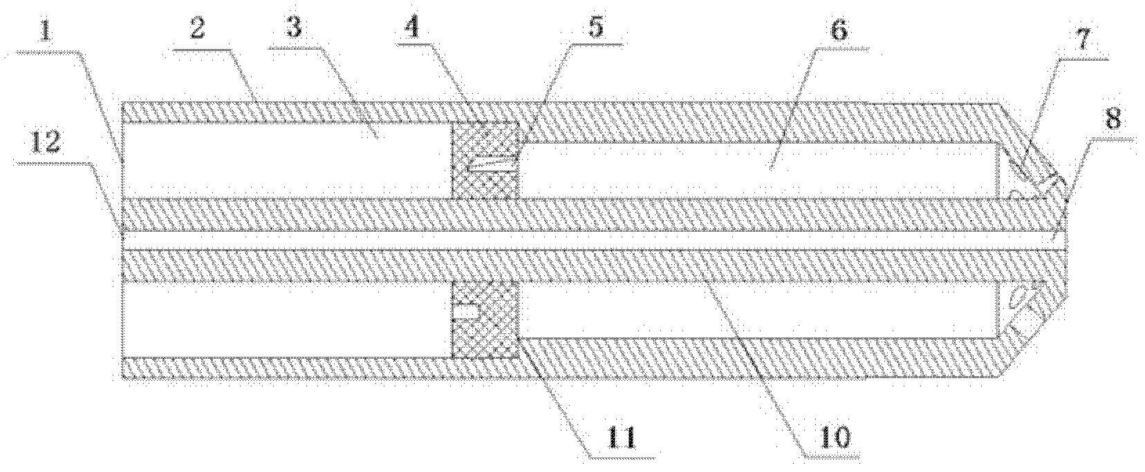
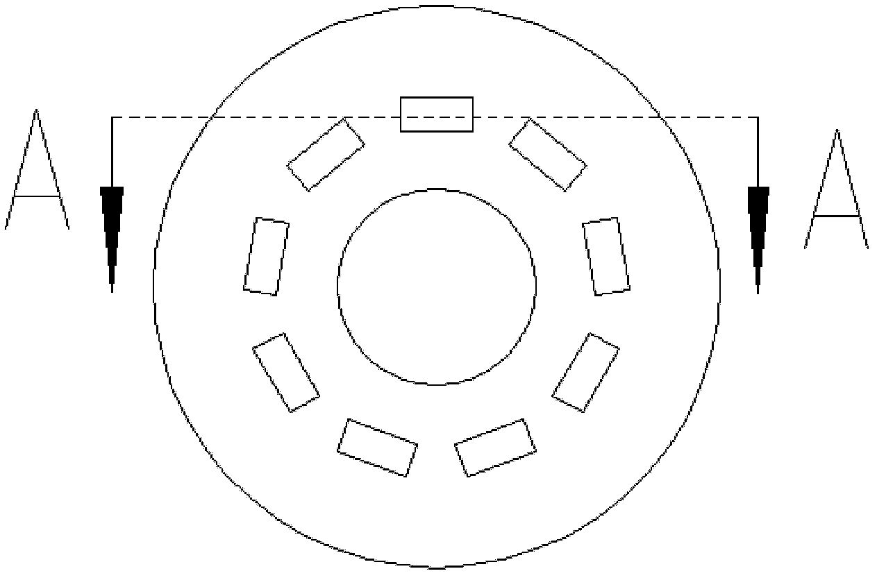
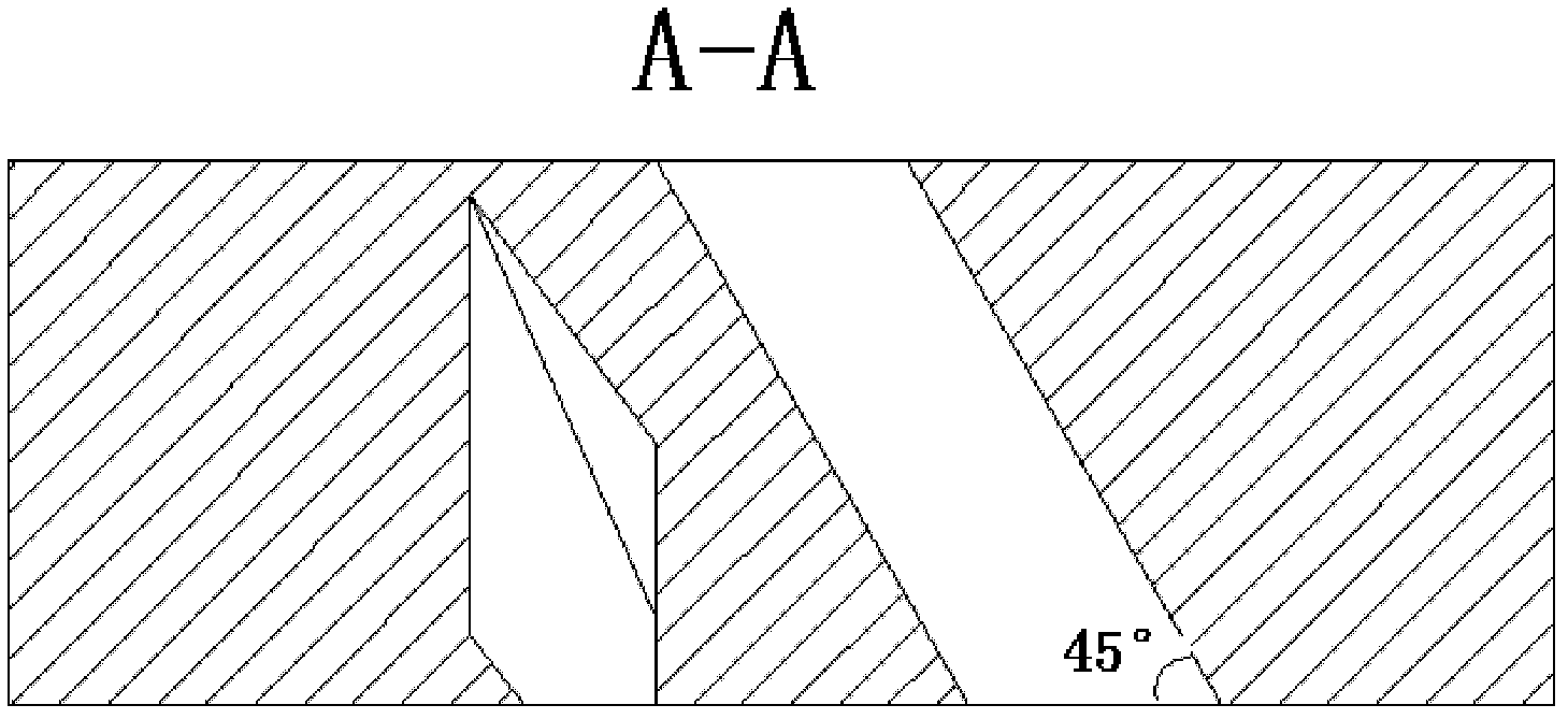
[0017] combine Figure 1~4 , the high-temperature zone of the combustion chamber using cracking cyclone flow blades is relatively front, indicating that the gas fuel and air are mixed ideally; the structure with pores on the head has a certain guiding effect on the outflow of cracking gas, and the high-temperature zone is relatively long and narrow. This is not easy to ablate the wall of the flame tube. The present invention combines the advantages and disadvantages of the above two structures, optimizes and integrates the two structures, and obtains an ideal internal swirling dual-fuel nozzle structure.

[0018] (1) A groove slightly larger than the diameter of the hollow cylindrical pipe of the gas path is processed in the gas path of the dual-fuel nozzle, and a swirl disk with a suitable thickness matching the groove diameter is made, and on the swirl disk Ho...


PUM


Abstract

The invention aims to provide an internal rotational flow dual fuel nozzle for a chemical regenerative cycle. The nozzle comprises a nozzle outer wall, an oil circuit pipeline, a gas spray hole, an oil spray hole and a rotational flow disk, wherein the oil circuit pipeline is arranged in the nozzle outer wall; a gas circuit cavity is formed between the oil circuit pipeline and the nozzle outer wall; the rotational flow disk is arranged between the oil circuit pipeline and the nozzle outer wall and divides the gas circuit cavity into a gas circuit front cavity and a gas circuit rear cavity; the gas circuit cavity is communicated with the gas spray hole; and the oil circuit pipeline is communicated with the oil spray hole. After a gas fuel sprayed from the nozzle is combusted, an internal rotational flow field can be formed, mixing is enhanced, combustion in a combustion chamber in the chemical regenerative cycle is intensified, the wall surface of a flame tube cannot be combusted, and the aims of combusting more fuels in a smaller space and shortening flame length are fulfilled.

Description

technical field [0001] The invention relates to an industrial nozzle in the field of power energy. Background technique [0002] A gas turbine is a typical conventional fuel power plant. It has the characteristics of small size, high power, light weight and fast start-up, and is widely used in core industrial fields such as aviation, electric power, ships and natural gas transmission. Therefore, the technical transformation and performance optimization of conventional gas turbine application technology has become an important topic to solve the energy crisis and environmental pollution problems. The chemical recuperation cycle is an advanced combustion-steam combined cycle method. It mainly uses the low-end waste heat of the gas turbine exhaust to generate superheated steam, and uses the high-end waste heat to promote the cracking of part of the fuel-steam under the action of the catalyst to generate gaseous fuels with high calorific value such as methane, hydrogen, and ca...

Claims


Application Information

Patent Timeline
Patent Type & Authority Applications(China)
IPC IPC(8): F23R3/36F23R3/38
Inventor 张智博李智明杨洪磊杨仁郑洪涛杨家龙刘倩潘福敏康振亚
Owner 三亚哈尔滨工程大学南海创新发展基地
Learn More