Rotary tube bundle heat exchanger

A heat exchanger and tube bundle technology, applied in the mechanical field, can solve the problems of increasing the heat transfer coefficient, increasing the fluid resistance, increasing the flow rate, etc., and achieving the effects of reducing the fluid resistance, reducing the volume and reducing the power.

Inactive Publication Date: 2012-07-04
NO 711 RES INST CHINA SHIPPING HEAVY IND GRP
View PDF8 Cites 17 Cited by
  • Summary
  • Abstract
  • Description
  • Claims
  • Application Information

AI Technical Summary

Problems solved by technology

[0002] The main heat exchange components of traditional heat exchangers are stationary, relying on the heat exchange medium to flow in the heat exchanger, and the two media exchange heat on the wall of the heat exchanger. In order to improve the heat transfer coefficient, various heat exchange methods have been adopted. The surface shape increases the flow rate of the medium at the same time to increase the Re number to increase the heat transfer coefficient; and increasing the flow rate of the medium will increase the fluid resistance. Since the relationship between resistance and flow rate is a quadratic relationship, it is impossible to design a heat exchanger infinitely Therefore, the current design of heat exchangers can only seek a balance between flow rate and resistance, that is, it is difficult to increase the heat transfer coefficient in a certain range. In order to meet the heat exchange of large flow and large heat transfer, only The heat exchange requirements are met by increasing the heat exchange area, so the heat exchange area of ​​a large heat exchanger often reaches several thousand square meters, the volume is very large, and the material consumption is also amazing, which brings many problems to manufacturing, operation, and maintenance.

Method used


Image

  • Rotary tube bundle heat exchanger
  • Rotary tube bundle heat exchanger
  • Rotary tube bundle heat exchanger

Examples


Embodiment Construction

[0014] The specific embodiments of the present invention will be further described below in conjunction with the accompanying drawings and examples. The following examples are only used to illustrate the technical solutions of the present invention more clearly, but not to limit the protection scope of the present invention.

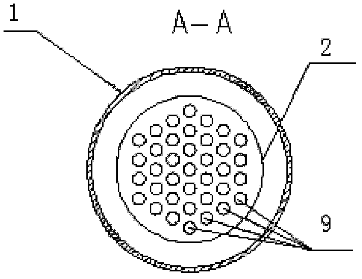
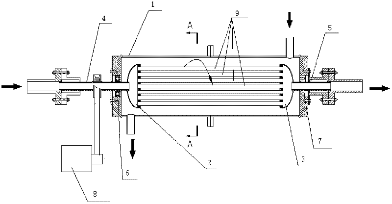
[0015] Such as figure 1 As shown, the technical solution of the present invention is to provide a tube bundle rotary heat exchanger, including a shell 1, a left tube plate 2, a right tube plate 3, a tube bundle 9, a motor 8, a rotating pipe a4, a rotating pipe b5, a bearing a6 and bearing b7; there are fluid inlets and outlets at the upper and lower ends of the housing 1, and the fluid inlets and outlets are located at both ends of the housing; there are through holes at the left and right ends of the housing 1, and there are rings on the through holes The groove; the left tube plate 2 and the right tube plate 3 are in the shape of a hemisphere, and the ...


PUM


Abstract

The invention belongs to the technical field of machinery, and relates to a rotary heat exchanger, in particular to a rotary tube bundle heat exchanger, which comprises a shell, a left tube plate, a right tube plate, a tube nest bundle, a motor, a rotating pipeline a, a rotating pipeline b, a bearing a and a bearing b. A fluid inlet and a fluid outlet are arranged at the upper end and the lower end of the shell respectively, through holes are arranged at the left end and the right end of the shell, annular grooves are arranged on the through holes, the left tube plate and the right tube plate are hemispherical, and the axis of the tube nest bundle is parallel to that of the shell. As the heat exchange coefficient of the rotary tube bundle heat exchanger is obtained without increasing the flow velocity of media, both a heat exchange medium a in an inner cylinder and a heat exchange medium b between the inner cylinder and an outer cylinder can enter the heat exchanger at a low speed, fluid resistance is greatly reduced, power needed for conveying fluids is remarkably decreased, and energy is saved.

Description

technical field [0001] The invention belongs to the technical field of machinery and relates to a rotary heat exchanger, in particular to a tube-bundle type rotary heat exchanger. Background technique [0002] The main heat exchange components of traditional heat exchangers are stationary, relying on the heat exchange medium to flow in the heat exchanger, and the two media exchange heat on the wall of the heat exchanger. In order to improve the heat transfer coefficient, various heat exchange methods have been adopted. The surface shape increases the flow rate of the medium at the same time to increase the Re number to increase the heat transfer coefficient; and increasing the flow rate of the medium will increase the fluid resistance. Since the relationship between resistance and flow rate is a quadratic relationship, it is impossible to design a heat exchanger infinitely Therefore, the current design of heat exchangers can only seek a balance between flow rate and resistan...

Claims


Application Information

Patent Timeline
Patent Type & Authority Applications(China)
IPC IPC(8): F28D7/16F28F5/00
Inventor 赵无非朱国庆
Owner NO 711 RES INST CHINA SHIPPING HEAVY IND GRP
Why Eureka
Try Eureka