
Temperature increasing and pressurizing foam cement slurry density testing device

A technology of heating, pressurizing, and testing devices, which is applied in measurement devices, specific gravity measurement, instruments, etc., can solve the problems of low density, difficult design and construction of cementing engineering, and low permeability, and achieve the effect of accurate measurement values.

Active Publication Date: 2012-07-04
CHINA PETROLEUM & CHEM CORP +1
View PDF8 Cites 14 Cited by
  • Summary
  • Abstract
  • Description
  • Claims
  • Application Information

AI Technical Summary

Problems solved by technology

In general, the research content of foam cement in various domestic oilfields is similar to that of foreign countries, mainly focusing on foam cement slurry configuration methods, construction methods, technological processes and related cementing theories, etc., but in terms of the breadth of research and application Compared with foreign countries, there is still a certain gap
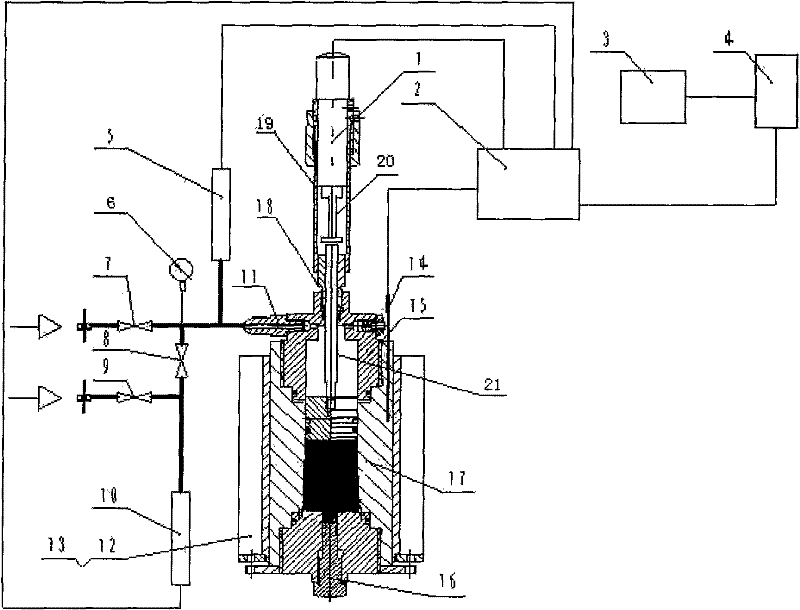
[0005] Foamed cement has the characteristics of low density, low permeability, low thermal conductivity, and high strength. However, under wellbore conditions, the density of foamed cement slurry is greatly affected by pressure and temperature, so ordinary density meters cannot respond to foamed cement slurry. The real density in the well brings great difficulties to the design and construction of the cementing project. Therefore, it is necessary to design a set of testers that can simulate the density change under the downhole temperature and pressure conditions to truly evaluate the foam cement slurry in the well. Changes in density under conditions of temperature and pressure changes

Method used


Image

  • Temperature increasing and pressurizing foam cement slurry density testing device
  • Temperature increasing and pressurizing foam cement slurry density testing device
  • Temperature increasing and pressurizing foam cement slurry density testing device

Examples


Embodiment 1

[0072] Example 1 Picture 8 As shown, the initial foam cement slurry density is 0.99g / cm 3 , The pressure does not change, the temperature rises from 30 ℃ to 75 ℃ density change graph, can see through this test device, the temperature increases, the density change range of the foam cement slurry is very small.

Embodiment 2

[0073] Example 2 such as Picture 9 As shown, the initial foam cement slurry density is 0.61g / cm 3 , The temperature does not change, and the pressure changes from 0-5000Kpa. It can be seen from this test device that the density of the foam cement slurry increases greatly when the pressure is in the range of 0-2000KPa.

Embodiment 3

[0074] Example 3 such as Picture 10 As shown, the initial foam cement slurry density is 0.95g / cm 3 , The change of foam cement slurry density when temperature and pressure change.


PUM

PropertyMeasurementUnit
Densityaaaaaaaaaa
Densityaaaaaaaaaa
Densityaaaaaaaaaa

Abstract

The present invention provides a temperature increasing and pressurizing foam cement slurry density testing device, and belongs to the field of oil field foam cement slurry cementing. The device comprises a pressure system, a temperature system, a test system and a computer acquisition system. According to the present invention, the foam cement slurry is placed into a cavity of a pressure resistance kettle; a piston is arranged on the upper part of the cement slurry; a pressurizing chamber is arranged on the upper part of the piston; a specially made high precision displacement sensor is arranged on the piston; and the upper part of the piston is fitted with a precision pressure source. According to the present invention, under the pressure effect, the volume of the foam cement is compressed, the piston moves downward, the displacement amount is measured by the displacement sensor and is converted into the digital amount. With the device of the present invention, the density change law of the foam cement at a certain temperature under a certain pressure can be accurately measured; the computer acquisition system is adopted to display and record the pressure-temperature-density curve, such that the strong basis is provided for real evaluation of the density of the foam cement under the underground construction conditions.

Description

Technical field [0001] The invention belongs to the field of oil field foam cement slurry cementing, and specifically relates to a heating and pressurizing foam cement slurry density test device. Background technique [0002] Foam cement cementing is mainly to reduce the density of cement slurry, thereby reducing the liquid column pressure of the cement slurry section in the annulus, to solve the problem of cementing leakage in the low-pressure and easy-to-leak oil layer, and to protect the oil layer. Foamed cement slurry is filled with gas in the cement slurry, and surfactants are added to stabilize the foam, forming a uniformly dispersed, stable and mutually independent low-density or ultra-low-density cement slurry system, which is composed of solid cement particles, water and gas Multiphase system composed of other substances. In this multiphase system, the gas is compressible, and its volume change is affected by temperature and pressure. The volume change of the gas in th...

Claims


Application Information

Patent Timeline
IPC IPC(8): G01N9/00
Inventor 丁士东刘伟王其春周仕明桑来玉周体秋
Owner CHINA PETROLEUM & CHEM CORP
Learn More