
Flat-top light beam shaping control method for achieving abrupt edge and low light-intensity variation and shaping device thereof

A light intensity fluctuation and flat-top beam technology, which is applied in optics, optical components, instruments, etc., can solve the problems of large fluctuations in the flat-top light intensity of the beam, the inability to achieve arbitrary setting positions in the far field, and the edge of the shaped beam is not steep, etc. , to achieve the effect of low light intensity fluctuation

Inactive Publication Date: 2012-07-04
HARBIN INST OF TECH
View PDF3 Cites 14 Cited by
  • Summary
  • Abstract
  • Description
  • Claims
  • Application Information

AI Technical Summary

Problems solved by technology

[0003] In order to solve the problem that the existing technology cannot realize arbitrary setting of the far field, the shape and diameter of the flat-topped beam shaped laser beam are invariable, the edge of the shaped beam is not steep, and the light intensity fluctuation of the flat-topped beam is large. question

Method used


Image

  • Flat-top light beam shaping control method for achieving abrupt edge and low light-intensity variation and shaping device thereof
  • Flat-top light beam shaping control method for achieving abrupt edge and low light-intensity variation and shaping device thereof
  • Flat-top light beam shaping control method for achieving abrupt edge and low light-intensity variation and shaping device thereof

Examples


specific Embodiment approach 1

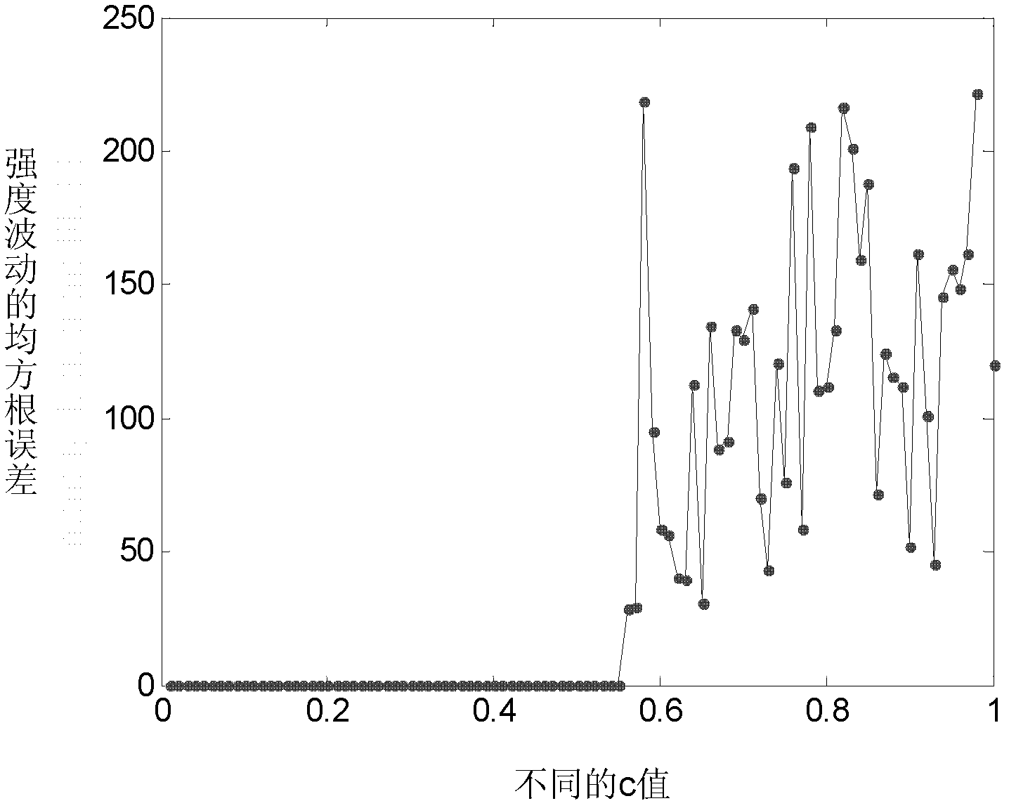
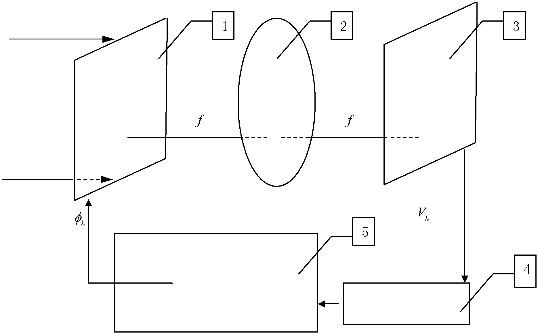
[0026] DETAILED DESCRIPTION OF THE PREFERRED EMBODIMENT 1. A flat-hat beam shaping device with steep edges and low fluctuations in light intensity, which includes an optical phased array 1, a lens 2, an output surface 3, an intensity analysis acquisition module 4 and a processor module 5, and a lens 2 Located between the surface where the optical phased array 1 is located and the output surface 3, the distance between the lens 2 and the phased array 1 and the output surface 3 is one times the focal length f, the incident beam passes through the optical phased array 1 and then passes through the lens 2 The Fourier transform is used to shape the light beam, and the shaped light field is obtained at the focal plane position of the lens 2, that is, the output plane 3, and the intensity distribution acquisition module 4 collects the beam intensity distribution of the shaped light field on the output surface 3, and the The collected data is transmitted to the processor module 5, and ...

specific Embodiment approach 2

[0028]Embodiment 2. A method for shaping and controlling a flat-hat beam shaping device with steep edges and low fluctuations in light intensity described in Embodiment 1. It includes the following steps:

[0029] 1. Obtain the initial phase φ according to formula (1) 1 ,

[0030] φ 1 = φ F +2π(rand-0.5) sinc -1 (|A F |) (1)

[0031] φ F For the expected intensity distribution of the beam I T Spatial phase distribution of light field after fast Fourier transform, A F For the expected intensity distribution of the beam I T The spatial amplitude distribution of the light field after fast Fourier transform, rand is a random distribution between 0 and 1, sinc -1 is the inverse function of the sinc function;

[0032] 2. φ of Step 1 1 According to the formula (2) to get U k , the phase distribution Ф of the output surface 3 is calculated by the fast Fourier transform of the lens 2 k , calculate the actually obtained intensity distribution I of the output surface 3 accor...

specific Embodiment approach 3

[0047] Embodiment 3. The difference between this embodiment and Embodiment 1 is that the focal length f can be achieved by superimposing the lens phase distribution on the optical phased array and the lens 2 in the device to form a combined focal length to achieve axial zooming, thereby achieving axial zooming. The purpose of outputting the intensity distribution of the shaped beam at a given position; by artificially setting the expected intensity distribution of the shaped beam as the shape and aperture of IT, a flat-hat beam of corresponding shape and aperture can be obtained at the output surface 3 position.

[0048] This implementation mode can reach the position where the far field can be set artificially, and realize any given shape of the laser beam and the flat-hat beam shaping characteristic of a given caliber.

[0049] The incident light source is a laser with a wavelength of λ, and its beam intensity distribution can be expressed as:

[0050] I Gauss =exp[-2(x 2 ...


PUM


Abstract

The invention discloses a flat-top light beam shaping control method for achieving an abrupt edge and low light-intensity variation and a shaping device thereof, and the flat-top light beam shaping control method and the shaping device relate to a flat-top light beam shaping device for achieving the abrupt edge and the low light-intensity variation, and further relate to a shaping control method, so as to solve the problems in the prior art that a position cannot be flexibly set to shape a light beam, the shape and the caliber of the shaped light beam cannot be changed flexibly, the edge is not abrupt, and further, the flat top light-intensity variation of the light beam is large. A lens in the shaping device provided by the invention is positioned between a surface where an optical phase array is positioned and an output surface; the light beam passes through the optical phase array, and then goes through a Fourier transform lens, so that the light beam is shaped; a light field is obtained at the output surface; and an intensity distribution collecting module collects the intensity distribution of the light beam of the shaped light field of the output surface and outputs the intensity distribution of the light beam to a processor module, and judges whether to adjust the phase of the optical phase array or not through calculating an RMSE (root-mean-square error ) value. By using the device provided by the invention, the anticipative shaping of the light beam is achieved by the shaping control method. The flat-top light beam shaping control method and the shaping device are applied to the technical field of diffraction optics and laser shaping.

Description

technical field [0001] The invention belongs to the technical field of diffractive optics and laser shaping, and in particular relates to a flat-top beam shaping device capable of realizing steep edges and low light intensity fluctuations, and also relates to a shaping control method. Background technique [0002] The flat-top beam shaping method and device are widely used in laser direct writing, laser inertial confinement fusion, laser communication, laser radar, laser processing and other fields. Especially in laser processing, it is necessary to achieve a position that can be set artificially in the far field, to achieve flat-top beam shaping with arbitrary shape and variable caliber of the laser beam, and the edge of the shaped beam is steep, and the light intensity of the beam flat-top fluctuates extremely Low. In the fields of laser holography, laser material processing, laser medical treatment, etc., laser beams with uniform spatial distribution of light intensity a...

Claims


Application Information

Patent Timeline
Patent Type & Authority Applications(China)
IPC IPC(8): G02B27/09
Inventor 王东张健吴丽莹张洪鑫甘雨申争光
Owner HARBIN INST OF TECH
Learn More