Unlock instant, AI-driven research and patent intelligence for your innovation.

output circuit

An output circuit and output drive circuit technology, applied in the field of output circuits, can solve the problems of increasing interconnection width, circuit size, and cost of semiconductor chips, etc.

Active Publication Date: 2016-04-20
RENESAS ELECTRONICS CORP
View PDF9 Cites 0 Cited by
  • Summary
  • Abstract
  • Description
  • Claims
  • Application Information

AI Technical Summary

Problems solved by technology

For this reason, the line width of the power supply line in the driver circuit (output transistor) and the width of the interconnection to the terminal are designed based on the lowest value of the current value at the time of increase, so that the interconnection width inevitably increases, which will cause The problem of circuit size expansion
In addition, the expansion of the circuit size will cause a problem that the cost of the semiconductor chip will increase

Method used


Image

  • output circuit
  • output circuit
  • output circuit

Examples


no. 1 example

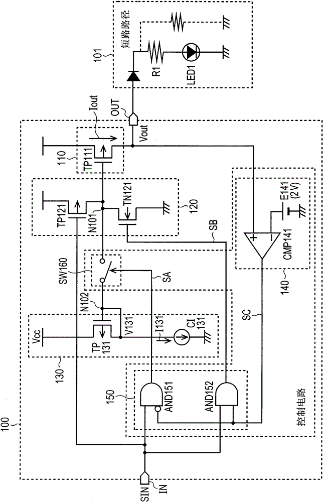
[0027] A specific embodiment of the present invention, ie, a first embodiment of the present invention, is hereinafter described in detail with reference to the accompanying drawings. figure 1 The configuration of the output circuit 100 according to the first embodiment of the present invention is shown. The first embodiment shows a case where the present invention is applied to an output circuit for driving an LED circuit.

[0028] like figure 1 As shown in , the output circuit 100 includes an output unit 110, an output driving circuit 120, a constant current limiting circuit 130, an output voltage comparison circuit 140, a driving control circuit 150, a switch circuit SW160, an input terminal IN and an output terminal OUT.

[0029] A load 101 is coupled to the output terminal OUT. The load 101 includes an LED circuit LED1, a current limiting resistor R1, and the like. The load 101 is driven by an output current Iout output from an output terminal OUT. In the case of th...


PUM


Abstract

The invention discloses an output circuit. An output circuit is provided for supplying an output current to a load coupled to an output terminal in response to an input signal. The output circuit includes: an output transistor, an output driving circuit, a constant current limiting circuit and a control circuit, the output transistor is used to supply an output current to an output terminal, the output driving circuit is used to drive the output transistor, and the constant current limiting circuit is used to generate A current control signal for limiting the output current to a predetermined current value, the control circuit for performing control such that after the input signal is supplied, when the voltage at the output terminal is at a predetermined voltage or less, control is performed based on the current control signal output current, and when the voltage at the output terminal exceeds a predetermined voltage, the output transistor is driven by the output driving circuit.

Description

[0001] Cross References to Related Applications [0002] The entire disclosure of Japanese Patent Application No. 2010-286091 filed on Dec. 22, 2010 including specification, drawings and abstract is incorporated herein by reference in its entirety. Background technique [0003] The invention relates to an output circuit. [0004] Using an output circuit of a semiconductor integrated circuit, on which an overcurrent protection circuit is mounted so that when a problem occurs in an interconnection or a load coupled to the output circuit and causes an overcurrent to flow, the output transistor of the output circuit is turned off, so that protect loads or integrated circuits. In Japanese Unexamined Patent Publication No. 2006-24997, a technique for incorporating an overcurrent protection circuit has been disclosed. The technology disclosed in Japanese Unexamined Patent Publication No. 2006-24997 relates to a semiconductor control device capable of suppressing power consumption o...

Claims


Application Information

Patent Timeline
Patent Type & Authority Patents(China)
IPC IPC(8): G05B19/04H05B44/00
CPCH03K2217/0027H03K17/0822H05B45/345H05B47/25H05B47/26H05B47/20H05B45/397Y02B20/30
Inventor 山内孝之
Owner RENESAS ELECTRONICS CORP